TORX179 Toshiba, TORX179 Datasheet - Page 3
TORX179
Manufacturer Part Number
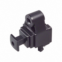
TORX179
Description
RECEIVER MODULE FIBER OPTIC
Manufacturer
Toshiba
Series
Toslink™r
Datasheet
1.TORX179.pdf
(5 pages)
Specifications of TORX179
Data Rate
12.8Mbps
Voltage - Supply
4.75 V ~ 5.25 V
Power - Minimum Receivable
-24dBm
Current - Supply
40mA
Applications
Digital Audio
Lead Free Status / RoHS Status
Contains lead / RoHS non-compliant
Available stocks
Company
Part Number
Manufacturer
Quantity
Price
Company:

Part Number:
TORX179
Manufacturer:
TOSHIBA
Quantity:
11 300
Company:
Part Number:
TORX179(F)
Manufacturer:
TOSHIBA
Quantity:
1 130
Part Number:
TORX179(F)
Manufacturer:
TOSHIBA/东芝
Quantity:
20 000
Company:
Part Number:
TORX179B
Manufacturer:
TOSHIBA
Quantity:
8 630
Company:
Part Number:
TORX179L
Manufacturer:
TOSHIBA
Quantity:
4 000
Company:
Part Number:
TORX179P
Manufacturer:
TOSHIBA
Quantity:
1 130
Part Number:
TORX179P
Manufacturer:
TOSHIBA/东芝
Quantity:
20 000
Part Number:
TORX179PL
Manufacturer:
TOSHIBA/东芝
Quantity:
20 000
Part Number:
TORX179S
Manufacturer:
TOSHIBA/东芝
Quantity:
20 000


5. Application Circuit
6. Required Optical Fiber with Fiber Optic Connectors
7. Board layout hole pattern (for reference)
8. Precautions on Use
TOCP172−
(1)
(2)
Maximum rating
Soldering
The maximum ratings are the limit values which must not be exceeded during operation of device.
None of these rating value must not be exceeded. If the maximum rating value is exceeded, the
characteristics of devices may never be restored properly. In extreme cases, the device may be
permanently damages.
Optical modules are comprised of internal semiconductor devices. However, in principle, optical
modules are optical components. During soldering, ensure that flux does not contact with the emitting
surface or the detecting surface. Also ensure that proper flux removal is conducted after soldering.
Some optical modules come with a protective cap. The protective cap is used to avoid malfunction
when the optical module is not in use. Note that it is not dust or waterproof.
As mentioned before, optical modules are optical components. Thus, in principle, soldering where
there may be flux residue and flux removal after soldering is not recommended. Toshiba recommend
that soldering be performed without the optical module mounted on the board. Then, after the board
has been cleaned, the optical module should be soldered on to the board manually.
If the optical module cannot be soldered manually, use non−halogen (chlorine−free) flux and make
sure, without cleaning, there is no residue such as chlorine. This is one of the ways to eliminate the
effects of flux. In such a cases, be sure to check the devices' reliability.
□□
B
3
Unit: mm
Tolerance: ±0.1 mm
Recommended PCB thickness: 1.6 mm
TORX179
2001-07-26
Related parts for TORX179
Image
Part Number
Description
Manufacturer
Datasheet
Request
R

Part Number:
Description:
Toshiba Semiconductor [TOSHIBA IGBT Module Silicon N Channel IGBT]
Manufacturer:
TOSHIBA Semiconductor CORPORATION
Datasheet:
Part Number:
Description:
TOSHIBA GTR MODULE SILICON NPN TRIPLE DIFFUSED TYPE
Manufacturer:
TOSHIBA Semiconductor CORPORATION
Datasheet:
Part Number:
Description:
TOSHIBA GTR Module Silicon N Channel IGBT
Manufacturer:
TOSHIBA Semiconductor CORPORATION
Datasheet:
Part Number:
Description:
TOSHIBA Intelligent Power Module Silicon N Channel IGBT
Manufacturer:
TOSHIBA Semiconductor CORPORATION
Datasheet:
Part Number:
Description:
TOSHIBA INTELLIGENT POWER MODULE SILICON N CHANNEL LGBT
Manufacturer:
TOSHIBA Semiconductor CORPORATION
Datasheet:
Part Number:
Description:
TOSHIBA IGBT Module Silicon N Channel IGBT
Manufacturer:
TOSHIBA Semiconductor CORPORATION
Datasheet:
Part Number:
Description:
TOSHIBA GTR MODULE SILICON N−CHANNEL IGBT
Manufacturer:
TOSHIBA Semiconductor CORPORATION
Datasheet:
Part Number:
Description:
TOSHIBA Intelligent Power Module Silicon N Channel IGBT
Manufacturer:
TOSHIBA Semiconductor CORPORATION
Datasheet:
Part Number:
Description:
TOSHIBA GTR Module Silicon N Channel IGBT
Manufacturer:
TOSHIBA Semiconductor CORPORATION
Datasheet:
Part Number:
Description:
TOSHIBA INTELLIGENT POWER MODULE
Manufacturer:
TOSHIBA Semiconductor CORPORATION
Datasheet:
Part Number:
Description:
TOSHIBA Intelligent Power Module Silicon N Channel IGBT
Manufacturer:
TOSHIBA Semiconductor CORPORATION
Datasheet:
Part Number:
Description:
TOSHIBA Intelligent Power Module Silicon N Channel IGBT
Manufacturer:
TOSHIBA Semiconductor CORPORATION
Datasheet:
Part Number:
Description:
TOSHIBA IGBT Module Silicon N Channel IGBT
Manufacturer:
TOSHIBA Semiconductor CORPORATION
Datasheet:
Part Number:
Description:
TOSHIBA Intelligent Power Module Silicon N Channel IGBT
Manufacturer:
TOSHIBA Semiconductor CORPORATION
Datasheet:
Part Number:
Description:
Toshiba Semiconductor [SILICON N CHANNEL 1GBT]
Manufacturer:
TOSHIBA Semiconductor CORPORATION
Datasheet: