ASMT-MWA0-NKKZ0 Avago Technologies US Inc., ASMT-MWA0-NKKZ0 Datasheet
ASMT-MWA0-NKKZ0
Specifications of ASMT-MWA0-NKKZ0


Related parts for ASMT-MWA0-NKKZ0


ASMT-MWA0-NKKZ0 Summary of contents
Page 1
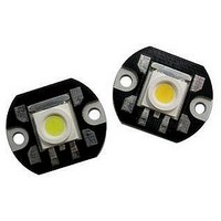
... V 2. Flux tolerance is ± Φ data are only applicable for ASMT-Mx00 component level device only. V Features • Available in red, amber, green, blue, cool white and warm white color. ...
Page 2
... Package Dimensions NOTES: 1. ALL DIMENSIONS IN MILLIMETERS. 2. TOLERANCE IS ±0.1MM UNLESS OTHERWISE SPECIFIED. Part Numbering System ASMT - Color Bin Selection Max Flux Bin Selection Min Flux Bin Selection Color R – Red A – Amber B - Blue G - Green W - Cool White Y - Warm White 2 ...
Page 3
... Operating Ambient Temperature Range Storage Temperature Range Note forward current – derate linearly based on Figure 5 for AlInGaP & Figure 11 for InGaN. 2. Pulse condition duty factor = 10%, Frequency = 1kHz. 3. Absolute Maximum Rating data are only applicable for ASMT-Mx00 component level device only. [3] Optical Characteristics ( °C) ...
Page 4
... AMBIENT TEMPERATURE - °C A Figure 5. Maximum forward current vs. ambient temperature for AllnGaP Derated based on T MAX = 110° 30°C/W / 40°C/W and 50°C Note: All parametric charts are only applicable for ASMT-Mx00 component level device only. 4 500 RED 450 AMBER 400 350 300 ...
Page 5
... AMBIENT TEMPERATURE - °C A Figure 11. Maximum forward current vs. ambient temperature for InGaN Derated based on T MAX = 110° 30°C/W / 40°C/W and 50°C Note: All parametric charts are only applicable for ASMT-Mx00 component level device only. 5 500 GREEN 450 BLUE 400 COOL WHITE ...
Page 6
... Figure 15. Relative LOP vs. junction temperature for InGaN 6 [1] Flux Bin Limit 100mA 150mA Bin Tolerance for each bin limits is ±10 % Note: Flux Bin Limit is only applicable for ASMT-Mx00 component level device only Color Bin Limits Amber Blue A B GREEN C BLUE COOL WHITE D ...
Page 7
Color Bin Selections [ Individual reel will contain parts from one full bin only. Cool White 0 Full Distribution A A only B B only C C only D D only E E only F F only G ...
Page 8
... F 10k 0.28 0.26 0.24 0.24 0.26 0.28 0.30 0.32 0.34 0.36 0.38 0.40 0.42 0. COORDINATE Note: 1. Color Limit and Color binning chart are only applicable for ASMT-Mx00 component level device only 8 [1] Warm White 0.329 0.329 Bin A 0.345 0.369 0.329 ...
Page 9
Sub-Color Binning (Only Applicable for Color Bin A to Bin D and Bin G to Bin H) Cool White Color Limits (Chromaticity Coordinates) Bin A1 X 0.364 0.367 Y 0.383 0.400 Bin A2 X 0.364 0.362 Y 0.383 0.372 Bin ...
Page 10
Package Tray Dimensions Handling Precaution The encapsulation material of the product is made of silicone for better reliability of the product. As silicone is a soft material, please do not press on the silicone or poke a sharp object onto ...