Z8F64220100ZDA Zilog, Z8F64220100ZDA Datasheet - Page 169
Z8F64220100ZDA
Manufacturer Part Number
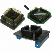
Z8F64220100ZDA
Description
ADAPTER ICE Z8 ENCORE 64K 64LQFP
Manufacturer
Zilog
Specifications of Z8F64220100ZDA
Module/board Type
*
For Use With/related Products
Z8 Encore!™
Lead Free Status / RoHS Status
Contains lead / RoHS non-compliant
Other names
269-3403


PS019921-0308
IEN—I
1 = The I
0 = The I
START—Send Start Condition
This bit sends the Start condition. Once asserted, it is cleared by the I
sends the START condition or if the IEN bit is deasserted. If this bit is 1, it cannot be
cleared to 0 by writing to the register. After this bit is set, the Start condition is sent if there
is data in the I
I
Controller is shifting out data, it generates a START condition after the byte shifts and the
acknowledge phase completes. If the STOP bit is also set, it also waits until the STOP
condition is sent before the sending the START condition.
STOP—Send Stop Condition
This bit causes the I
register has completed transmission or after a byte has been received in a receive
operation. Once set, this bit is reset by the I
sent or by deasserting the IEN bit. If this bit is 1, it cannot be cleared to 0 by writing to the
register.
BIRQ—Baud Rate Generator Interrupt Request
This bit allows the I
Controller is disabled. This bit is ignored when the I
1 = An interrupt occurs every time the baud rate generator counts down to one.
0 = No baud rate generator interrupt occurs.
TXI—Enable TDRE interrupts
This bit enables the transmit interrupt when the I
1 = Transmit interrupt (and DMA transmit request) is enabled.
0 = Transmit interrupt (and DMA transmit request) is disabled.
NAK—Send NAK
This bit sends a Not Acknowledge condition after the next byte of data has been read from
the I
bit is deasserted. If this bit is 1, it cannot be cleared to 0 by writing to the register.
FLUSH—Flush Data
Setting this bit to 1 clears the I
flushing of the I
data has been sent to the I
FILTEN—I
This bit enables low-pass digital filters on the SDA and SCL input signals. These filters
reject any input pulse with periods less than a full system clock cycle. The filters introduce
a 3-system clock cycle latency on the inputs.
1 = low-pass filters are enabled.
0 = low-pass filters are disabled.
2
C Controller waits until the Data register is written. If this bit is set while the I
2
C slave. Once asserted, it is deasserted after a Not Acknowledge is sent or the IEN
2
C Enable
2
2
C transmitter and receiver are enabled.
C transmitter and receiver are disabled.
2
C Signal Filter Enable
2
C Data or I
2
C Data register when a Not Acknowledge interrupt is received after the
2
2
C Controller to issue a Stop condition after the byte in the I
C Controller to be used as an additional timer when the I
2
2
C Data register. Reading this bit always returns 0.
C Shift register. If there is no data in one of these registers, the
2
C Data register and sets the TDRE bit to 1. This bit allows
2
C Controller after a Stop condition has been
2
C Data register is empty (TDRE = 1).
2
C Controller is enabled.
Z8 Encore! XP
Product Specification
2
C Controller after it
®
F64XX Series
I2C Controller
2
C
2
2
C
C Shift
155
Related parts for Z8F64220100ZDA
Image
Part Number
Description
Manufacturer
Datasheet
Request
R

Part Number:
Description:
Communication Controllers, ZILOG INTELLIGENT PERIPHERAL CONTROLLER (ZIP)
Manufacturer:
Zilog, Inc.
Datasheet:

Part Number:
Description:
KIT DEV FOR Z8 ENCORE 16K TO 64K
Manufacturer:
Zilog
Datasheet:

Part Number:
Description:
KIT DEV Z8 ENCORE XP 28-PIN
Manufacturer:
Zilog
Datasheet:

Part Number:
Description:
DEV KIT FOR Z8 ENCORE 8K/4K
Manufacturer:
Zilog
Datasheet:

Part Number:
Description:
KIT DEV Z8 ENCORE XP 28-PIN
Manufacturer:
Zilog
Datasheet:

Part Number:
Description:
DEV KIT FOR Z8 ENCORE 4K TO 8K
Manufacturer:
Zilog
Datasheet:
Part Number:
Description:
CMOS Z8 microcontroller. ROM 16 Kbytes, RAM 256 bytes, speed 16 MHz, 32 lines I/O, 3.0V to 5.5V
Manufacturer:
Zilog, Inc.
Datasheet:
Part Number:
Description:
Low-cost microcontroller. 512 bytes ROM, 61 bytes RAM, 8 MHz
Manufacturer:
Zilog, Inc.
Datasheet:
Part Number:
Description:
Z8 4K OTP Microcontroller
Manufacturer:
Zilog, Inc.
Datasheet:
Part Number:
Description:
CMOS SUPER8 ROMLESS MCU
Manufacturer:
Zilog, Inc.
Datasheet:
Part Number:
Description:
SL1866 CMOSZ8 OTP Microcontroller
Manufacturer:
Zilog, Inc.
Datasheet:
Part Number:
Description:
SL1866 CMOSZ8 OTP Microcontroller
Manufacturer:
Zilog, Inc.
Datasheet:
Part Number:
Description:
OTP (KB) = 1, RAM = 125, Speed = 12, I/O = 14, 8-bit Timers = 2, Comm Interfaces Other Features = Por, LV Protect, Voltage = 4.5-5.5V
Manufacturer:
Zilog, Inc.
Datasheet:
Part Number:
Description:
Manufacturer:
Zilog, Inc.
Datasheet: