Z8F64220100ZDA Zilog, Z8F64220100ZDA Datasheet - Page 189
Z8F64220100ZDA
Manufacturer Part Number
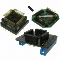
Z8F64220100ZDA
Description
ADAPTER ICE Z8 ENCORE 64K 64LQFP
Manufacturer
Zilog
Specifications of Z8F64220100ZDA
Module/board Type
*
For Use With/related Products
Z8 Encore!™
Lead Free Status / RoHS Status
Contains lead / RoHS non-compliant
Other names
269-3403


Table 86. ADC Control Register (ADCCTL)
ADC Control Register Definitions
PS019921-0308
BITS
FIELD
RESET
R/W
ADDR
ADC Control Register
CEN
7
The ADC Control register selects the analog input channel and initiates the analog-to-dig-
ital conversion.
CEN—Conversion Enable
0 = Conversion is complete. Writing a 0 produces no effect. The ADC automatically clears
this bit to 0 when a conversion has been completed.
1 = Begin conversion. Writing a 1 to this bit starts a conversion. If a conversion is already
in progress, the conversion restarts. This bit remains 1 until the conversion is complete.
Reserved—Must be 0.
VREF
0 = Internal voltage reference generator enabled. The VREF pin should be left uncon-
nected (or capacitively coupled to analog ground) if the internal voltage reference is
selected as the ADC reference voltage.
1 = Internal voltage reference generator disabled. An external voltage reference must be
provided through the VREF pin.
CONT
0 = Single-shot conversion. ADC data is output once at completion of the 5129 system
clock cycles.
1 = Continuous conversion. ADC data updated every 256 system clock cycles.
ANAIN—Analog Input Select
These bits select the analog input for conversion. For information on the Port pins avail-
able with each package style, see
unavailable analog inputs.
0000 = ANA0
0001 = ANA1
0010 = ANA2
0011 = ANA3
0100 = ANA4
0
Reserved
6
VREF
5
1
CONT
Signal and Pin Descriptions
4
F70H
R/W
3
Z8 Encore! XP
2
0
ANAIN[3:0]
on page 7. Do not enable
Product Specification
Analog-to-Digital Converter
1
®
F64XX Series
0
175
Related parts for Z8F64220100ZDA
Image
Part Number
Description
Manufacturer
Datasheet
Request
R

Part Number:
Description:
Communication Controllers, ZILOG INTELLIGENT PERIPHERAL CONTROLLER (ZIP)
Manufacturer:
Zilog, Inc.
Datasheet:

Part Number:
Description:
KIT DEV FOR Z8 ENCORE 16K TO 64K
Manufacturer:
Zilog
Datasheet:

Part Number:
Description:
KIT DEV Z8 ENCORE XP 28-PIN
Manufacturer:
Zilog
Datasheet:

Part Number:
Description:
DEV KIT FOR Z8 ENCORE 8K/4K
Manufacturer:
Zilog
Datasheet:

Part Number:
Description:
KIT DEV Z8 ENCORE XP 28-PIN
Manufacturer:
Zilog
Datasheet:

Part Number:
Description:
DEV KIT FOR Z8 ENCORE 4K TO 8K
Manufacturer:
Zilog
Datasheet:
Part Number:
Description:
CMOS Z8 microcontroller. ROM 16 Kbytes, RAM 256 bytes, speed 16 MHz, 32 lines I/O, 3.0V to 5.5V
Manufacturer:
Zilog, Inc.
Datasheet:
Part Number:
Description:
Low-cost microcontroller. 512 bytes ROM, 61 bytes RAM, 8 MHz
Manufacturer:
Zilog, Inc.
Datasheet:
Part Number:
Description:
Z8 4K OTP Microcontroller
Manufacturer:
Zilog, Inc.
Datasheet:
Part Number:
Description:
CMOS SUPER8 ROMLESS MCU
Manufacturer:
Zilog, Inc.
Datasheet:
Part Number:
Description:
SL1866 CMOSZ8 OTP Microcontroller
Manufacturer:
Zilog, Inc.
Datasheet:
Part Number:
Description:
SL1866 CMOSZ8 OTP Microcontroller
Manufacturer:
Zilog, Inc.
Datasheet:
Part Number:
Description:
OTP (KB) = 1, RAM = 125, Speed = 12, I/O = 14, 8-bit Timers = 2, Comm Interfaces Other Features = Por, LV Protect, Voltage = 4.5-5.5V
Manufacturer:
Zilog, Inc.
Datasheet:
Part Number:
Description:
Manufacturer:
Zilog, Inc.
Datasheet: