Z8F64220100ZDA Zilog, Z8F64220100ZDA Datasheet - Page 98
Z8F64220100ZDA
Manufacturer Part Number
Z8F64220100ZDA
Description
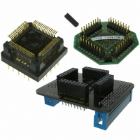
ADAPTER ICE Z8 ENCORE 64K 64LQFP
Manufacturer
Zilog
Specifications of Z8F64220100ZDA
Module/board Type
*
For Use With/related Products
Z8 Encore!™
Lead Free Status / RoHS Status
Contains lead / RoHS non-compliant
Other names
269-3403


PS019921-0308
Follow the steps below for configuring a timer for COMPARE mode and initiating the
count:
1. Write to the Timer Control 1 register to:
2. Write to the Timer High and Low Byte registers to set the starting count value.
3. Write to the Timer Reload High and Low Byte registers to set the Compare value.
4. If desired, enable the timer interrupt and set the timer interrupt priority by writing to
5. If using the Timer Output function, configure the associated GPIO port pin for the
6. Write to the Timer Control 1 register to enable the timer and initiate counting.
In COMPARE mode, the system clock always provides the timer input. The Compare time
is given by the following equation:
GATED Mode
In GATED mode, the timer counts only when the Timer Input signal is in its active state
(asserted), as determined by the TPOL bit in the Timer Control 1 register. When the Timer
Input signal is asserted, counting begins. A timer interrupt is generated when the Timer
Input signal is deasserted or a timer reload occurs. To determine if a Timer Input signal
deassertion generated the interrupt, read the associated GPIO input value and compare to
the value stored in the TPOL bit.
The timer counts up to the 16-bit Reload value stored in the Timer Reload High and Low
Byte registers. The timer input is the system clock. When reaching the Reload value, the
timer generates an interrupt, the count value in the Timer High and Low Byte registers is
reset to
Also, if the Timer Output alternate function is enabled, the Timer Output pin changes state
(from Low to High or from High to Low) at timer reset.
Follow the steps below for configuring a timer for GATED mode and initiating the count:
1. Write to the Timer Control 1 register to:
COMPARE Mode Time (s)
–
–
–
–
the relevant interrupt registers.
Timer Output alternate function.
–
–
0001H
Disable the timer
Configure the timer for COMPARE mode
Set the prescale value
Set the initial logic level (High or Low) for the Timer Output alternate function, if
desired
Disable the timer
Configure the timer for GATED mode
and counting resumes (assuming the Timer Input signal is still asserted).
=
(
----------------------------------------------------------------------------------------------------- -
Compare Value Start Value
System Clock Frequency (Hz)
–
Z8 Encore! XP
)
×
Prescale
Product Specification
®
F64XX Series
Timers
84
Related parts for Z8F64220100ZDA
Image
Part Number
Description
Manufacturer
Datasheet
Request
R

Part Number:
Description:
Communication Controllers, ZILOG INTELLIGENT PERIPHERAL CONTROLLER (ZIP)
Manufacturer:
Zilog, Inc.
Datasheet:

Part Number:
Description:
KIT DEV FOR Z8 ENCORE 16K TO 64K
Manufacturer:
Zilog
Datasheet:

Part Number:
Description:
KIT DEV Z8 ENCORE XP 28-PIN
Manufacturer:
Zilog
Datasheet:

Part Number:
Description:
DEV KIT FOR Z8 ENCORE 8K/4K
Manufacturer:
Zilog
Datasheet:

Part Number:
Description:
KIT DEV Z8 ENCORE XP 28-PIN
Manufacturer:
Zilog
Datasheet:

Part Number:
Description:
DEV KIT FOR Z8 ENCORE 4K TO 8K
Manufacturer:
Zilog
Datasheet:
Part Number:
Description:
CMOS Z8 microcontroller. ROM 16 Kbytes, RAM 256 bytes, speed 16 MHz, 32 lines I/O, 3.0V to 5.5V
Manufacturer:
Zilog, Inc.
Datasheet:
Part Number:
Description:
Low-cost microcontroller. 512 bytes ROM, 61 bytes RAM, 8 MHz
Manufacturer:
Zilog, Inc.
Datasheet:
Part Number:
Description:
Z8 4K OTP Microcontroller
Manufacturer:
Zilog, Inc.
Datasheet:
Part Number:
Description:
CMOS SUPER8 ROMLESS MCU
Manufacturer:
Zilog, Inc.
Datasheet:
Part Number:
Description:
SL1866 CMOSZ8 OTP Microcontroller
Manufacturer:
Zilog, Inc.
Datasheet:
Part Number:
Description:
SL1866 CMOSZ8 OTP Microcontroller
Manufacturer:
Zilog, Inc.
Datasheet:
Part Number:
Description:
OTP (KB) = 1, RAM = 125, Speed = 12, I/O = 14, 8-bit Timers = 2, Comm Interfaces Other Features = Por, LV Protect, Voltage = 4.5-5.5V
Manufacturer:
Zilog, Inc.
Datasheet:
Part Number:
Description:
Manufacturer:
Zilog, Inc.
Datasheet: