W682510DK Nuvoton Technology Corporation of America, W682510DK Datasheet - Page 5
W682510DK
Manufacturer Part Number
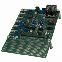
W682510DK
Description
KIT DEVELOPMENT FOR W682510
Manufacturer
Nuvoton Technology Corporation of America
Specifications of W682510DK
Main Purpose
Telecom, CODEC
Embedded
No
Utilized Ic / Part
W682510
Primary Attributes
Dual Voice Band PCM CODEC
Secondary Attributes
Parallel & Serial Modes, 2 RJ9 Handset Jacks
Lead Free Status / RoHS Status
Contains lead / RoHS non-compliant


To set up the handsets to communicate over parallel and serial mode, connect the digital channels as
follows:
Parallel mode (In same time slot)
Serial mode (Not in same time slot)
2.3 Power
There are three ways of supplying power to the board:
The jumper JP6 selects whether a 5V or 3V regulator is used. Connecting J13 to a 5 VDC supply drives
the circuits on the board directly or through the 3V regulator selected by jumper JP7.
Do not change these jumpers, as they have been set according to the CODEC device on the board.
2.4 Bit Clock and Frame Sync
A 2.048 MHz TTL oscillator generates the allowable bit clock frequencies from 64 kHz up to 2.048 MHz.
The bit clock is selectable through jumper JP5. The Frame Sync signal is 8 kHz with a 50% duty cycle.
2.5 Analog Audio Circuits
The CODEC supports variable input gain (<10X). This gain can be manually set for each channel with
variable resistors VR1 (channel 1) and VR2 (channel2). The CODEC itself does not support handset
operation so analog circuits for microphone bias (no AGC) are required. A unity gain output amplifier
drives the handset speakers.
For optimal sound quality, adjust VR1 and VR2 individually to provide approximately 2.4 Vp-p
(W6825010) or 1.0 Vp-p (W682310) at the AI1 and AI2 pins from the source. The source can be either a
microphone or an external input
2.6 Prototyping Area
All CODEC I/O pins are connected to the prototyping area for easy connection of additional hardware.
The switches and jumpers that disconnect the signals generated on the CODEC board will simplify
connection of external circuits.
2.7 Telephone handset microphone setup
Two switches (SW12 and SW13) toggle between the two common types of handsets available. Switching
will reverse the polarity of the microphone connectors. If two handsets are used and the handsets are not
transmitting audio, try the other position of the switches to ensure the correct microphone polarity is used.
Winbond Electronics Corporation America
2727 N First Street, San Jose CA 95134
•
•
•
•
•
•
•
•
•
Set SW7 to VCC position to set CHPS to VCC
Connect DIN1 to DOUT2 (PCMR1 to PCMT2)
Connect DIN2 to DOUT1 (PCMR2 to PCMT1)
Set SW7 to GND position to set CHPS to GND
Connect DIN2 to DOUT1 (PCMR2 to PCMT1)
Leave other digital pins unconnected
9 V battery
9 VDC at 500 mA power supply
Header J7 for 5 VDC (in USB application)
682x10DK
5
Related parts for W682510DK
Image
Part Number
Description
Manufacturer
Datasheet
Request
R

Part Number:
Description:
Manufacturer:
Nuvoton Technology Corporation of America
Datasheet:
Part Number:
Description:
Manufacturer:
Nuvoton Technology Corporation of America
Datasheet:
Part Number:
Description:
Manufacturer:
Nuvoton Technology Corporation of America
Datasheet:
Part Number:
Description:
Manufacturer:
Nuvoton Technology Corporation of America
Datasheet:
Part Number:
Description:
Manufacturer:
Nuvoton Technology Corporation of America
Datasheet:
Part Number:
Description:
Manufacturer:
Nuvoton Technology Corporation of America
Datasheet:
Part Number:
Description:
Manufacturer:
Nuvoton Technology Corporation of America
Datasheet: