STEVAL-ISQ002V1 STMicroelectronics, STEVAL-ISQ002V1 Datasheet - Page 35
STEVAL-ISQ002V1
Manufacturer Part Number
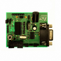
STEVAL-ISQ002V1
Description
BOARD EVAL BASED ON ST72264G1
Manufacturer
STMicroelectronics
Specifications of STEVAL-ISQ002V1
Main Purpose
Interface, PMBus
Embedded
Yes, MCU, 8-Bit
Utilized Ic / Part
ST72F264
Primary Attributes
The PMBus™ Interface Using the ST7 I2C Peripheral
Secondary Attributes
Firmware in C Language
Product
Power Management Modules
Lead Free Status / RoHS Status
Lead free / RoHS Compliant
Other names
497-6423
Available stocks
Company
Part Number
Manufacturer
Quantity
Price
Company:

Part Number:
STEVAL-ISQ002V1
Manufacturer:
STMicroelectronics
Quantity:
1


8.4 ACTIVE-HALT AND HALT MODES
ACTIVE-HALT and HALT modes are the two low-
est power consumption modes of the MCU. They
are both entered by executing the ‘HALT’ instruc-
tion. The decision to enter either in ACTIVE-HALT
or HALT mode is given by the MCC/RTC interrupt
enable flag (OIE bit in MCCSR register).
8.4.1 ACTIVE-HALT MODE
ACTIVE-HALT mode is the lowest power con-
sumption mode of the MCU with a real time clock
available. It is entered by executing the ‘HALT’ in-
struction when the OIE bit of the Main Clock Con-
troller Status register (MCCSR) is set.
The MCU can exit ACTIVE-HALT mode on recep-
tion of either an MCC/RTC interrupt, a specific in-
terrupt (see
32) or a RESET. When exiting ACTIVE-HALT
mode by means of an interrupt, no 4096 CPU cy-
cle delay occurs. The CPU resumes operation by
servicing the interrupt or by fetching the reset vec-
tor which woke it up (see
When entering ACTIVE-HALT mode, the I[1:0] bits
in the CC register are forced to ‘10b’ to enable in-
terrupts. Therefore, if an interrupt is pending, the
MCU wakes up immediately.
In ACTIVE-HALT mode, only the main oscillator
and its associated counter (MCC/RTC) are run-
ning to keep a wake-up time base. All other periph-
erals are not clocked except those which get their
clock supply from another clock generator (such
as external or auxiliary oscillator).
The safeguard against staying locked in ACTIVE-
HALT mode is provided by the oscillator interrupt.
Note: As soon as the interrupt capability of one of
the oscillators is selected (MCCSR.OIE bit set),
entering ACTIVE-HALT mode while the Watchdog
is active does not generate a RESET.
This means that the device cannot spend more
than a defined delay in this power saving mode.
MCCSR
OIE bit
0
1
HALT mode
ACTIVE-HALT mode
Power Saving Mode entered when HALT
Table 5, “Interrupt Mapping,” on page
instruction is executed
Figure
24).
Figure 23. ACTIVE-HALT Timing Overview
Figure 24. ACTIVE-HALT Mode Flowchart
Notes:
1. This delay occurs only if the MCU exits ACTIVE-
HALT mode by means of a RESET.
2. Peripheral clocked with an external clock source
can still be active.
3. Only the MCC/RTC interrupt and some specific
interrupts can exit the MCU from ACTIVE-HALT
mode (such as external interrupt). Refer to
5, “Interrupt Mapping,” on page 32
4. Before servicing an interrupt, the CC register is
pushed on the stack. The I[1:0] bits of the CC reg-
ister are set to the current software priority level of
the interrupt routine and restored when the CC
register is popped.
[MCCSR.OIE=1]
INSTRUCTION
HALT INSTRUCTION
RUN
N
(MCCSR.OIE=1)
HALT
ST72260Gx, ST72262Gx, ST72264Gx
INTERRUPT
ACTIVE
HALT
Y
CYCLE DELAY
INTERRUPT
3)
4096 CPU
RESET
OR SERVICE INTERRUPT
FETCH RESET VECTOR
OR
OSCILLATOR
PERIPHERALS
CPU
I[1:0] BITS
OSCILLATOR
PERIPHERALS
CPU
I[1:0] BITS
OSCILLATOR
PERIPHERALS
CPU
I[1:0] BITS
N
4096 CPU CLOCK
CYCLE DELAY
RESET
Y
1)
for more details.
VECTOR
FETCH
RUN
2)
XX
XX
OFF
OFF
OFF
ON
ON
ON
ON
ON
ON
10
35/172
4)
4)
Table
Related parts for STEVAL-ISQ002V1
Image
Part Number
Description
Manufacturer
Datasheet
Request
R

Part Number:
Description:
BOARD RGB CTR ST7,STP08C596MTR
Manufacturer:
STMicroelectronics
Datasheet:

Part Number:
Description:
Power Management IC Development Tools Full Speed USB to RS232 Bridge Demo
Manufacturer:
STMicroelectronics
Datasheet:
Part Number:
Description:
Power Management IC Development Tools 2.5W solar eval BRD USB SPV1040 LD39050
Manufacturer:
STMicroelectronics
Datasheet:

Part Number:
Description:
BOARD EVAL FOR MEMS SENSORS
Manufacturer:
STMicroelectronics
Datasheet:

Part Number:
Description:
KIT DEV STARTER ST10F276Z5
Manufacturer:
STMicroelectronics
Datasheet:

Part Number:
Description:
BOARD EVAL HDMI $ VIDEO SWITCH
Manufacturer:
STMicroelectronics
Datasheet:

Part Number:
Description:
BOARD DEMO ACCELEROMETER DIL24
Manufacturer:
STMicroelectronics
Datasheet:

Part Number:
Description:
BOARD STLM75/STDS75/ST72F651
Manufacturer:
STMicroelectronics
Datasheet:

Part Number:
Description:
EVAL BOARD 3AXIS MEMS ACCELLRMTR
Manufacturer:
STMicroelectronics
Datasheet:

Part Number:
Description:
BOARD EVAL 8BIT MICRO + TDE1708
Manufacturer:
STMicroelectronics
Datasheet:
Part Number:
Description:
STMicroelectronics [RIPPLE-CARRY BINARY COUNTER/DIVIDERS]
Manufacturer:
STMicroelectronics
Datasheet:
Part Number:
Description:
STMicroelectronics [LIQUID-CRYSTAL DISPLAY DRIVERS]
Manufacturer:
STMicroelectronics
Datasheet:
Part Number:
Description:
BOARD EVAL FOR MEMS SENSORS
Manufacturer:
STMicroelectronics
Datasheet: