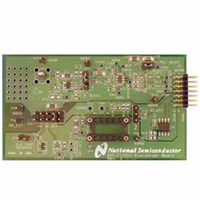
ADC121C02XEB/NOPB National Semiconductor, ADC121C02XEB/NOPB Datasheet - Page 11

ADC121C02XEB/NOPB
Manufacturer Part Number
ADC121C02XEB/NOPB
Description
BOARD EVAL FOR ADC121C-21
Manufacturer
National Semiconductor
Series
PowerWise®r
Specifications of ADC121C02XEB/NOPB
Number Of Adc's
1
Number Of Bits
12
Sampling Rate (per Second)
188.9k
Data Interface
Serial
Inputs Per Adc
1 Single Ended
Input Range
0 ~ 5.5 V
Power (typ) @ Conditions
3.67mw @ 188.9kSPS
Voltage Supply Source
Single Supply
Operating Temperature
-40°C ~ 105°C
Utilized Ic / Part
ADC121C021,ADC121C027
Silicon Manufacturer
National
Silicon Core Number
ADC121C021, ADC121C027
Kit Application Type
Data Converter
Application Sub Type
ADC
Kit Contents
Board
Lead Free Status / RoHS Status
Lead free / RoHS Compliant
Other names
ADC121C02XEB
5.4 Troubleshooting WaveVision
5.4.1 Problems
Problem 1: The “ADC121C021 Eval Board”
Control Panel appears briefly, but disappears after
powering on the WaveVision board. Try Solutions
A, B, and C.
WaveVision system must be hard reset to
recover. Press SW1 on the WV4 board to reset
the system.
Problem 2: The following error occurs when I try
to acquire data samples. Try Solution D.
Problem 3: The following error occurs when I try
to read or write registers through the Control
Panel. Try Solution D.
Problem 4: One of the following errors occurs
when I try to read or write registers through the
Control
…CMD_REG_RW … while sending bulk read.”
“An exception occurred. Control Panel…”
Try Solutions A, B, and C.
solutions, the WaveVision system must be hard
reset to recover. Press SW1 on the WV4 board to
reset the system.
Problem 5: The Eval Board is not recognized
correctly in the System Settings Window (Figure
9). Try Solutions D and E.
11
Panel.
After trying these solutions, the
“java.lang.Exception:
After trying these
A
USB
5.4.2 Solutions
Solution A: Ensure power is supplied to the V
supply on the board. A single jumper must be
placed across either pins 1&2, pins 3&4, pins 7&8,
or pins 9&10 of JP5 to select the board’s power
source. If using the Shunt Reference, pins 1&2 of
JP7 must be shorted. The V
by probing VIA10.
Solution B: Ensure the pull-up resistors are
powered (R8 and R9). In Computer mode, JP2
must be shorted by a jumper for the WaveVision
software to work properly.
Solution C: Ensure the board is firmly connected
to the WV4 board via the WV4S connector (J1).
See Figure 6.
Solution D: Ensure the I
correctly in WaveVision.
ADC121C021, the address must be set to 0x54.
If evaluating the ADC121C027, the address will
be 0x50 if no user modifications have been made
to the board and ADDR is floating. If ADDR is tied
to GND, the address must be set to 0x51.
ADDR is tied to V
0x52.
Solution E: Ensure the 3P3V supply is connected
to the 3.3V regulated supply from the WV4 board.
The 3P3V supply is measured by probing pin 1 of
JP5. Test this with a volt-meter. The EEPROM
(U4) must be powered with 3.3V for WaveVision
to work properly.
A
, the address must be set to
2
C Slave address is set
A
http://www.national.com
supply is measured
If evaluating the
If
A


