SSM2302Z-EVAL Analog Devices Inc, SSM2302Z-EVAL Datasheet - Page 14
SSM2302Z-EVAL
Manufacturer Part Number
SSM2302Z-EVAL
Description
BOARD EVAL FOR SSM2302
Manufacturer
Analog Devices Inc
Datasheet
1.SSM2302CPZ-REEL7.pdf
(20 pages)
Specifications of SSM2302Z-EVAL
Amplifier Type
Class D
Output Type
2-Channel (Stereo)
Max Output Power X Channels @ Load
1.4W x 2 @ 8 Ohm
Voltage - Supply
2.5 V ~ 5 V
Operating Temperature
-40°C ~ 85°C
Board Type
Fully Populated
Utilized Ic / Part
SSM2302
Silicon Manufacturer
Analog Devices
Application Sub Type
Audio Power Amplifier - Class D
Kit Application Type
Amplifier
Silicon Core Number
SSM2302
Kit Contents
Board
Lead Free Status / RoHS Status
Lead free / RoHS Compliant
Lead Free Status / RoHS Status
Lead free / RoHS Compliant, Lead free / RoHS Compliant


SSM2302
EVALUATION BOARD INFORMATION
INTRODUCTION
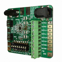
The SSM2302 audio power amplifier is a complete low power,
Class-D, stereo audio amplifier capable of delivering 1.4 W/channel
into 8 Ω load. In addition to the minimal parts required for the
application circuit, measurement filters are provided on the
evaluation board so that conventional audio measurements can
be made without additional components.
This section provides an overview of Analog Devices SSM2302
evaluation board. It includes a brief description of the board as
well as a list of the board specifications.
Table 5. SSM2302 Evaluation Board Specifications
Parameter
Supply Voltage Range, V
Power Supply Current Rating
Continuous Output Power, P
Minimum Load Impedance
OPERATION
Use the following steps when operating the SSM2302
evaluation board.
Power and Ground
1.
Inputs and Outputs
1.
2.
3.
(R
L
Set the power supply voltage between 2.5 V and 5.0 V. When
connecting the power supply to the SSM2302 evaluation
board, make sure to attach the ground connection to the
GND header pin first and then connect the positive supply
to the VDD header pin.
Ensure that the audio source is set to the minimum level.
Connect the audio source to Inputs INL± and INR±.
Connect the speakers to Outputs OUTL± and OUTR±.
= 8 Ω, f = 1 kHz, 22 kHz BW)
DD
O
Specification
2.5 V to 5.0 V
1.5 A
1.4 W
8 Ω
Rev. 0 | Page 14 of 20
Gain Control
The gain select header controls the gain setting of the SSM2302.
1.
2.
External Gain Settings
It is possible to adjust the SSM2302 gain using external resistors
at the input. To set a gain lower than 12 dB refer to Figure 22
and Figure 23 on the product data sheet for proper circuit con-
figuration. For external gain configuration from a fixed 12 dB
gain, use the following formula:
To set a gain lower than 6 dB refer to Figure 24 and Figure 25
on the product data sheet for proper circuit configuration. For
external gain configuration from a fixed 6 dB gain, use the
following formula:
Shutdown Control
The shutdown select header controls the shutdown function of
the SSM2302. The shutdown pin on the SSM2302 is active low,
meaning that a low voltage (GND) on this pin places the SSM2302
into shutdown mode.
1.
2.
Input Configurations
1.
2.
Select jumper to LG for 6 dB gain.
Select jumper to HG for 12 dB gain.
External Gain Settings = 20 log[4/(1 + R/150 kΩ)]
External Gain Settings = 20 log[2/(1 + R/150 kΩ)]
Select jumper to 1-2 position. Shutdown pulled to V
Select jumper to 2-3 position. Shutdown pulled to GND.
For differential input configuration with input capacitors
do not place a jumper on JP8, JP9, JP10, and JP11.
For differential input configuration without input capacitors
place a jumper on JP8, JP9, JP10, and JP11.
DD
.
Related parts for SSM2302Z-EVAL
Image
Part Number
Description
Manufacturer
Datasheet
Request
R

Part Number:
Description:
±1.7g Dual-Axis IMEMS Accelerometer Evaluation Board
Manufacturer:
Analog Devices Inc
Datasheet:

Part Number:
Description:
Inertial Sensor Evaluation System
Manufacturer:
Analog Devices Inc
Datasheet:
Part Number:
Description:
Manufacturer:
Analog Devices Inc
Datasheet:
Part Number:
Description:
Manufacturer:
Analog Devices Inc
Datasheet:
Part Number:
Description:
Manufacturer:
Analog Devices Inc
Datasheet:
Part Number:
Description:
Manufacturer:
Analog Devices Inc
Datasheet:
Part Number:
Description:
Manufacturer:
Analog Devices Inc
Datasheet:
Part Number:
Description:
Manufacturer:
Analog Devices Inc
Datasheet:
Part Number:
Description:
Manufacturer:
Analog Devices Inc
Datasheet:
Part Number:
Description:
Manufacturer:
Analog Devices Inc
Datasheet:
Part Number:
Description:
Manufacturer:
Analog Devices Inc
Datasheet:
Part Number:
Description:
Manufacturer:
Analog Devices Inc
Datasheet:
Part Number:
Description:
Manufacturer:
Analog Devices Inc
Datasheet: