RDK-83 Power Integrations, RDK-83 Datasheet - Page 13
RDK-83
Manufacturer Part Number
RDK-83
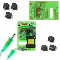
Description
KIT DESIGN REF LINKSWITCH LP
Manufacturer
Power Integrations
Series
LinkSwitch®-LPr
Specifications of RDK-83
Main Purpose
AC/DC, Primary Side
Outputs And Type
1, Isolated
Power - Output
1.6W
Voltage - Output
7.7V
Current - Output
210mA
Voltage - Input
85 ~ 265VAC
Regulator Topology
Flyback
Frequency - Switching
66kHz
Board Type
Bare (Unpopulated) and Fully Populated
Utilized Ic / Part
LNK562, LNK563, LNK564
Lead Free Status / RoHS Status
Not applicable / Not applicable
Other names
596-1128


7.4 Transformer Build Diagram
7.5 Transformer Construction
Bobbin orientation is such that primary pins are on the left hand side of the winding spindle
Page 13 of 36
Secondary
WD1
Cancellation and
Bias Winding
Insulation
WD #2
Primary Winding
Insulation
WD #3
Shield Winding
Insulation
WD #4
Secondary Winding
Outer insulation
Gap Core
Core Assembly and
trim flying leads
Varnish
WD #4
Pin 2
Pin 3
Pin 4
Pin 1
Pin 1
Primary pin side of the bobbin oriented to the left hand side. Temporarily
start at pin 7. Wind 29 bifilar turns of item [3] from right to left. Wind with
tight tension evenly across the bobbin. Terminate finish on pin 4. Take
the end of the winding that was started on pin 7 and terminate it on pin 3.
1 Layer of tape [6] for insulation.
Start at Pin 2. Wind 58 turns of item [3] from left to right. Then wind 59
turns on the next layer from right to left. Wind 59 turns from left to right
on the third layer. Wind with tight tension evenly across the bobbin.
Bring the wire across the bobbin and terminate the finish on pin 1.
Use one layer of tape [6] for basic insulation.
Temporarily start at Pin 7. Wind 15 bifilar turns of item [4]. Wind from
right to left with tight tension across the entire bobbin width. Terminate on
pin 1. Cut the wire from Pin 7 and leave it unconnected.
Use three layers of tape [6] for basic insulation.
Temporarily start at Pin 7 (allow 1” of wire at the start for the flying lead).
Wind 17 turns of item [5] from right to left with tight tension. Allow 1” of
wire at the finish for the flying lead, at the right side of bobbin. Remove
the start from pin 7 and mark. Exit start at right hand side of the bobbin.
Wrap windings with three layers of tape [6].
Gap core such that the inductance between pins 1 & 2 is 3.5 mH ±10%.
The gap is approximately 0.2 mm.
Assemble and secure the core halves. Trim flying leads to 0.65”±0.05”.
Tin leads 0.15”±0.05”. Cut bobbin pins 5,6,7 and 8.
Dip varnish assembly with item [7].
Figure 6 – Transformer Build Diagram.
Tel: +1 408 414 9200 Fax: +1 408 414 9201
Tape
Tape
Tape
Tape
NC
FLYING LEAD (MARKED)
FLYING LEAD
Cancellation
Power Integrations
www.powerint.com
Primary
WD #1
WD #2
WD #3
Shield
Related parts for RDK-83
Image
Part Number
Description
Manufacturer
Datasheet
Request
R

Part Number:
Description:
KIT REF DESIGN 36-72W MOTOR DRVR
Manufacturer:
Power Integrations
Datasheet:

Part Number:
Description:
KIT REF DESIGN FOR LNK457D
Manufacturer:
Power Integrations
Datasheet:

Part Number:
Description:
REFERENCE DESIGN LINKSWITCH-PH
Manufacturer:
Power Integrations
Datasheet:

Part Number:
Description:
Specifications: Manufacturer: Power Integrations ; Output Voltage: 380 VDC ; Input / Supply Voltage (Max): 264 VAC ; Input / Supply Voltage (Min): 90 VAC ; Mounting Style: Through Hole ; Output Current: 0.913 A ; Output Power: 347 W
Manufacturer:
Power Integrations, Inc.

Part Number:
Description:
KIT REF DESIGN TOP HX FOR TOP258
Manufacturer:
Power Integrations
Datasheet:

Part Number:
Description:
Power Management Modules & Development Tools TOPSwitch-JX REF. DESIGN KIT
Manufacturer:
Power Integrations
Datasheet:
Part Number:
Description:
Power Management IC Development Tools REF DESIGN RDR-292 PFF LED STREET LIGHT
Manufacturer:
Power Integrations

Part Number:
Description:
KIT REF DESIGN FOR LNK403EG
Manufacturer:
Power Integrations
Datasheet:

Part Number:
Description:
KIT REF DESIGN FOR LNK406EG
Manufacturer:
Power Integrations
Datasheet:

Part Number:
Description:
KIT REF DESIGN DG CAPZERO
Manufacturer:
Power Integrations
Datasheet:

Part Number:
Description:
KIT REF DESIGN LINKSWITCH-CV
Manufacturer:
Power Integrations
Datasheet:

Part Number:
Description:
KIT REF DESIGN LINKSWITCH 2
Manufacturer:
Power Integrations
Datasheet:

Part Number:
Description:
KIT REF DESIGN PFS762HG
Manufacturer:
Power Integrations
Datasheet:
Part Number:
Description:
Specifications: Family: Eval Boards - DC/DC & AC/DC (Off-Line) SMPS ; Series: HiperLCS™ ; Main Purpose: DC/DC, Step Down ; Outputs and Type: 1, Isolated ; Power - Output: 150W ; Voltage - Output: 24V ; Current - Output: 6.25A ; Voltage - Input:
Manufacturer:
Power Integrations, Inc.
Datasheet:

Part Number:
Description:
KIT REF DESIGN 1.2W PS TN FAMILY
Manufacturer:
Power Integrations
Datasheet: