RDK-83 Power Integrations, RDK-83 Datasheet - Page 15
RDK-83
Manufacturer Part Number
RDK-83
Description
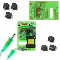
KIT DESIGN REF LINKSWITCH LP
Manufacturer
Power Integrations
Series
LinkSwitch®-LPr
Specifications of RDK-83
Main Purpose
AC/DC, Primary Side
Outputs And Type
1, Isolated
Power - Output
1.6W
Voltage - Output
7.7V
Current - Output
210mA
Voltage - Input
85 ~ 265VAC
Regulator Topology
Flyback
Frequency - Switching
66kHz
Board Type
Bare (Unpopulated) and Fully Populated
Utilized Ic / Part
LNK562, LNK563, LNK564
Lead Free Status / RoHS Status
Not applicable / Not applicable
Other names
596-1128


I^2fMIN
I^2fTYP
VOR
VDS
VD
KP
ENTER TRANSFORMER CORE/CONSTRUCTION VARIABLES
Core Type
Core
Bobbin
AE
LE
AL
BW
M
L
NS
NB
VB
R1
R2
Recommended Bias Diode
DC INPUT VOLTAGE PARAMETERS
VMIN
VMAX
CURRENT WAVEFORM SHAPE PARAMETERS
DMAX
IAVG
IP
IR
IRMS
TRANSFORMER PRIMARY DESIGN PARAMETERS
LP
LP_TOLERANCE
Page 15 of 36
EE16
90.00
0.90
EE16_B
OBBIN
EE16
1N4003
0.192 cm^2
22.26 Volts
37.47 k-ohms
EE16
1099 A^2Hz
1221 A^2Hz
1140 nH/T^2
3486 uHenries
1.99
3.00 k-ohms
0.45
0.04 Amps
0.12 Amps
0.12 Amps
0.05 Amps
375 Volts
0.9 Volts
3.5 cm
8.6 mm
90 Volts
10 Volts
17
44
73 Volts
10 %
0 mm
2
P/N:
P/N:
Tel: +1 408 414 9200 Fax: +1 408 414 9201
I^2f Minimum value (product of current limit
squared and frequency is trimmed for tighter -
tolerance)
I^2f typical value (product of current limit squared
and frequency is trimmed for tighter tolerance)
Reflected Output Voltage
LinkSwitch-LP on-state Drain to Source Voltage
Output Winding Diode Forward Voltage Drop
Ripple to Peak Current Ratio (0.9<KRP<1.0 :
1.0<KDP<6.0)
User-Selected transformer core
PC40EE16-Z
EE16_BOBBIN
Core Effective Cross Sectional Area
Core Effective Path Length
Ungapped Core Effective Inductance
Bobbin Physical Winding Width
Safety Margin Width (Half the Primary to
Secondary Creepage Distance)
Number of primary layers
Number of Secondary Turns
Number of Bias winding turns
Bias Winding Voltage
Resistor divider component between bias
wiinding and FB pin of LinkSwitch-LP
Resistor divider component between FB pin of
LinkSwitch-LP and primary RTN
Place this diode on the return leg of the bias
winding for optimal EMI. See LinkSwitch-LP
Design guide for more information
Minimum DC Input Voltage
Maximum DC Input Voltage
Maximum Duty Cycle
Average Primary Current
Minimum Peak Primary Current
Primary Ripple Current
Primary RMS Current
Typical Primary Inductance. +/- 10%
Primary inductance tolerance
Power Integrations
www.powerint.com
Related parts for RDK-83
Image
Part Number
Description
Manufacturer
Datasheet
Request
R

Part Number:
Description:
KIT REF DESIGN 36-72W MOTOR DRVR
Manufacturer:
Power Integrations
Datasheet:

Part Number:
Description:
KIT REF DESIGN FOR LNK457D
Manufacturer:
Power Integrations
Datasheet:

Part Number:
Description:
REFERENCE DESIGN LINKSWITCH-PH
Manufacturer:
Power Integrations
Datasheet:

Part Number:
Description:
Specifications: Manufacturer: Power Integrations ; Output Voltage: 380 VDC ; Input / Supply Voltage (Max): 264 VAC ; Input / Supply Voltage (Min): 90 VAC ; Mounting Style: Through Hole ; Output Current: 0.913 A ; Output Power: 347 W
Manufacturer:
Power Integrations, Inc.

Part Number:
Description:
KIT REF DESIGN TOP HX FOR TOP258
Manufacturer:
Power Integrations
Datasheet:

Part Number:
Description:
Power Management Modules & Development Tools TOPSwitch-JX REF. DESIGN KIT
Manufacturer:
Power Integrations
Datasheet:
Part Number:
Description:
Power Management IC Development Tools REF DESIGN RDR-292 PFF LED STREET LIGHT
Manufacturer:
Power Integrations

Part Number:
Description:
KIT REF DESIGN FOR LNK403EG
Manufacturer:
Power Integrations
Datasheet:

Part Number:
Description:
KIT REF DESIGN FOR LNK406EG
Manufacturer:
Power Integrations
Datasheet:

Part Number:
Description:
KIT REF DESIGN DG CAPZERO
Manufacturer:
Power Integrations
Datasheet:

Part Number:
Description:
KIT REF DESIGN LINKSWITCH-CV
Manufacturer:
Power Integrations
Datasheet:

Part Number:
Description:
KIT REF DESIGN LINKSWITCH 2
Manufacturer:
Power Integrations
Datasheet:

Part Number:
Description:
KIT REF DESIGN PFS762HG
Manufacturer:
Power Integrations
Datasheet:
Part Number:
Description:
Specifications: Family: Eval Boards - DC/DC & AC/DC (Off-Line) SMPS ; Series: HiperLCS™ ; Main Purpose: DC/DC, Step Down ; Outputs and Type: 1, Isolated ; Power - Output: 150W ; Voltage - Output: 24V ; Current - Output: 6.25A ; Voltage - Input:
Manufacturer:
Power Integrations, Inc.
Datasheet:

Part Number:
Description:
KIT REF DESIGN 1.2W PS TN FAMILY
Manufacturer:
Power Integrations
Datasheet: