RDK-83 Power Integrations, RDK-83 Datasheet - Page 16
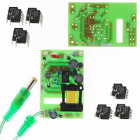
RDK-83
Manufacturer Part Number
RDK-83
Description
KIT DESIGN REF LINKSWITCH LP
Manufacturer
Power Integrations
Series
LinkSwitch®-LPr
Specifications of RDK-83
Main Purpose
AC/DC, Primary Side
Outputs And Type
1, Isolated
Power - Output
1.6W
Voltage - Output
7.7V
Current - Output
210mA
Voltage - Input
85 ~ 265VAC
Regulator Topology
Flyback
Frequency - Switching
66kHz
Board Type
Bare (Unpopulated) and Fully Populated
Utilized Ic / Part
LNK562, LNK563, LNK564
Lead Free Status / RoHS Status
Not applicable / Not applicable
Other names
596-1128


NP
ALG
BM
BAC
ur
LG
BWE
OD
INS
DIA
AWG
CM
CMA
TRANSFORMER SECONDARY DESIGN PARAMETERS
Lumped parameters
ISP
ISRMS
IRIPPLE
CMS
AWGS
DIAS
ODS
INSS
VOLTAGE STRESS PARAMETERS
VDRAIN
PIVS
TRANSFORMER SECONDARY DESIGN PARAMETERS (MULTIPLE OUTPUTS)
1st output
VO1
IO1
PO1
VD1
NS1
Power Integrations
Tel: +1 408 414 9200 Fax: +1 408 414 9201
www.powerint.com
0.211 Amps
17.00
1490 Gauss
1654
0.20 Mm
17.2 Mm
0.10 Mm
0.02 Mm
0.07 Mm
1.30 Amps
0.47 Amps
0.42 Amps
0.26 Mm
0.51 Mm
0.12 Mm
1.63 Watts
178
110 nH/T^2
745 Gauss
150 Cmils/Amp Primary Winding Current Capacity (150 < CMA <
7.7 Volts
0.9 Volts
41 AWG
93 Cmils
30 AWG
44 Volts
8 Cmils
- Volts
Primary Winding Number of Turns
Gapped Core Effective Inductance
Maximum Operating Flux Density, BM<1500 is
recommended
AC Flux Density for Core Loss Curves (0.5 X
Peak to Peak)
Relative Permeability of Ungapped Core
Gap Length (Lg > 0.1 mm)
Effective Bobbin Width
Maximum Primary Wire Diameter including
insulation
Estimated Total Insulation Thickness (= 2 * film
thickness)
Bare conductor diameter
Primary Wire Gauge (Rounded to next smaller
standard AWG value)
Bare conductor effective area in circular mils
500)
Peak Secondary Current
Secondary RMS Current
Output Capacitor RMS Ripple Current
Secondary Bare Conductor minimum circular
mils
Secondary Wire Gauge (Rounded up to next
larger standard AWG value)
Secondary Minimum Bare Conductor Diameter
Secondary Maximum Outside Diameter for Triple
Insulated Wire
Maximum Secondary Insulation Wall Thickness
Peak Drain Voltage is highly dependent on
Transformer capacitance and leakage
inductance. Please verify this on the bench and
ensure that it is below 650 V to allow 50 V
margin for transformer variation.
Output Rectifier Maximum Peak Inverse Voltage
Main Output Voltage (if unused, defaults to
single output design)
Output DC Current
Output Power
Output Diode Forward Voltage Drop
Output Winding Number of Turns
Page 16 of 36
Related parts for RDK-83
Image
Part Number
Description
Manufacturer
Datasheet
Request
R

Part Number:
Description:
KIT REF DESIGN 36-72W MOTOR DRVR
Manufacturer:
Power Integrations
Datasheet:

Part Number:
Description:
KIT REF DESIGN FOR LNK457D
Manufacturer:
Power Integrations
Datasheet:

Part Number:
Description:
REFERENCE DESIGN LINKSWITCH-PH
Manufacturer:
Power Integrations
Datasheet:

Part Number:
Description:
Specifications: Manufacturer: Power Integrations ; Output Voltage: 380 VDC ; Input / Supply Voltage (Max): 264 VAC ; Input / Supply Voltage (Min): 90 VAC ; Mounting Style: Through Hole ; Output Current: 0.913 A ; Output Power: 347 W
Manufacturer:
Power Integrations, Inc.

Part Number:
Description:
KIT REF DESIGN TOP HX FOR TOP258
Manufacturer:
Power Integrations
Datasheet:

Part Number:
Description:
Power Management Modules & Development Tools TOPSwitch-JX REF. DESIGN KIT
Manufacturer:
Power Integrations
Datasheet:
Part Number:
Description:
Power Management IC Development Tools REF DESIGN RDR-292 PFF LED STREET LIGHT
Manufacturer:
Power Integrations

Part Number:
Description:
KIT REF DESIGN FOR LNK403EG
Manufacturer:
Power Integrations
Datasheet:

Part Number:
Description:
KIT REF DESIGN FOR LNK406EG
Manufacturer:
Power Integrations
Datasheet:

Part Number:
Description:
KIT REF DESIGN DG CAPZERO
Manufacturer:
Power Integrations
Datasheet:

Part Number:
Description:
KIT REF DESIGN LINKSWITCH-CV
Manufacturer:
Power Integrations
Datasheet:

Part Number:
Description:
KIT REF DESIGN LINKSWITCH 2
Manufacturer:
Power Integrations
Datasheet:

Part Number:
Description:
KIT REF DESIGN PFS762HG
Manufacturer:
Power Integrations
Datasheet:
Part Number:
Description:
Specifications: Family: Eval Boards - DC/DC & AC/DC (Off-Line) SMPS ; Series: HiperLCS™ ; Main Purpose: DC/DC, Step Down ; Outputs and Type: 1, Isolated ; Power - Output: 150W ; Voltage - Output: 24V ; Current - Output: 6.25A ; Voltage - Input:
Manufacturer:
Power Integrations, Inc.
Datasheet:

Part Number:
Description:
KIT REF DESIGN 1.2W PS TN FAMILY
Manufacturer:
Power Integrations
Datasheet: