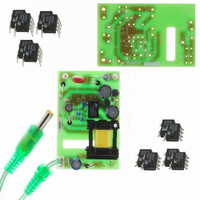
RDK-83 Power Integrations, RDK-83 Datasheet - Page 23

RDK-83
Manufacturer Part Number
RDK-83
Description
KIT DESIGN REF LINKSWITCH LP
Manufacturer
Power Integrations
Series
LinkSwitch®-LPr
Specifications of RDK-83
Main Purpose
AC/DC, Primary Side
Outputs And Type
1, Isolated
Power - Output
1.6W
Voltage - Output
7.7V
Current - Output
210mA
Voltage - Input
85 ~ 265VAC
Regulator Topology
Flyback
Frequency - Switching
66kHz
Board Type
Bare (Unpopulated) and Fully Populated
Utilized Ic / Part
LNK562, LNK563, LNK564
Lead Free Status / RoHS Status
Not applicable / Not applicable
Other names
596-1128
10 Thermal Performance
10.1 LNK562 Temperature Rise
The RD-83 was installed within a sealed plastic enclosure, placed inside a sealed
cardboard box, and placed into a thermal chamber at 50 °C.
prevented the chamber circulation fan from blowing air across the plastic enclosure. A
thermocouple, attached to pin 2 of U1, was used to monitor its temperature.
This result indicates acceptable thermal margin of approximately of 16 °C to the
recommended maximum SOURCE pin temperature of 100 °C
10.2 Thermal Image
An infrared thermograph of the board was taken to measure the temperature of other
components. This identified U1 and D4 as the highest temperature components. Using
the results from the previous section, this indicates that D4 would also have an
acceptable temperature rise at 50 °C ambient.
Figure 11 – Thermal Image of the RD-83 at Full Load, 85 VAC Input and Ambient Temperature of 22 °C.
Page 23 of 36
Ambient
LinkSwitch (U1)
Item
85 VAC
50
78
Temperature (°C)
Tel: +1 408 414 9200 Fax: +1 408 414 9201
265 VAC
50
84
Power Integrations
www.powerint.com
The cardboard box


