RDK-83 Power Integrations, RDK-83 Datasheet - Page 7
RDK-83
Manufacturer Part Number
RDK-83
Description
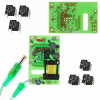
KIT DESIGN REF LINKSWITCH LP
Manufacturer
Power Integrations
Series
LinkSwitch®-LPr
Specifications of RDK-83
Main Purpose
AC/DC, Primary Side
Outputs And Type
1, Isolated
Power - Output
1.6W
Voltage - Output
7.7V
Current - Output
210mA
Voltage - Input
85 ~ 265VAC
Regulator Topology
Flyback
Frequency - Switching
66kHz
Board Type
Bare (Unpopulated) and Fully Populated
Utilized Ic / Part
LNK562, LNK563, LNK564
Lead Free Status / RoHS Status
Not applicable / Not applicable
Other names
596-1128


29-Sept-06
RDR-83 7.7 V, 210 mA Adapter with 10 kV surge withstand
4 Circuit Description
4.1 Input Stage
Components C1, C6, L1 and L3 comprise a balanced π filter. Resistor R5 dampens low
frequency conducted EMI. The supply needs no Y1-type capacitor (that normally bridges
the primary to secondary isolation barrier) due to U1’s frequency jitter function and the
E-Shield™ techniques used in the design of transformer T1. This minimizes audible
noise in applications connected to a phone line, by eliminating a path for line frequency
leakage currents to pass onto the output of the supply.
The supply easily meets
EN55022B conducted EMI limits, with more than 15 dBµV of margin.
A metal oxide varistor (RV1) and a wire wound resistor (RF1) attenuate differential line
surges. The varistor is required to meet the 2 kV differential surge requirement. In
applications where only 1 kV of surge immunity is required, RV1 can be eliminated. The
wire wound resistor (RF1) must be able to withstand high transient dissipation from initial
inrush current (when AC power is applied) and during line surges.
4.2 LinkSwitch-LP
The LinkSwitch-LP family of ICs were designed to replace linear transformer solutions in
low-power charger and adapter applications.
Feedback to the LNK562P IC (U1) is
derived from a resistor divider (R1 and R2) across the bias supply (D3 and C3), which
lowers cost by eliminating the need for an optocoupler.
Linear transformers typically use thermal fuses (over temperature cut-outs) for overload
protection. However, once a thermal fuse trips, the entire charger or adapter must be
thrown away, since thermal fuses cannot be reset or repaired.
Latching thermal
shutdown functions are typically used in ringing choke converter (RCC) based supplies.
However, AC input power must be removed and reapplied to reset most thermal latches.
Since customers typically don’t know this, they often return good units they thought were
defective, simply because the thermal latch tripped and shut the unit off. The LinkSwitch-
LP family’s hysteretic thermal shutdown function has a very tight tolerance (142 °C,
±5%), and automatically restarts the power supply once the IC temperature drops below
the lower temperature threshold. This maintains the average PCB temperature at a safe
level under all conditions, and reduces the return rate of good units from the field. The
auto-recovery feature also eliminates the noise sensitivity and component aging
problems associated with discrete latching circuits.
Pin 6 is eliminated from the IC package to extend the creepage distance between the
DRAIN pin and all other low voltage pins; both at the package and on the PCB. This
reduces the likelihood that tracking or arcing will occur due to moisture or board surface
contamination (from dust and dirt), which improves reliability in high humidity and high
pollution environments. During an output short circuit or an open loop condition, the
LinkSwitch-LP’s auto-restart function limits output power to about 12% of the maximum.
This protects both the load and the supply during prolonged overload conditions.
Power Integrations
Tel: +1 408 414 9200 Fax: +1 408 414 9201
Page 7 of 36
www.powerint.com
Related parts for RDK-83
Image
Part Number
Description
Manufacturer
Datasheet
Request
R

Part Number:
Description:
KIT REF DESIGN 36-72W MOTOR DRVR
Manufacturer:
Power Integrations
Datasheet:

Part Number:
Description:
KIT REF DESIGN FOR LNK457D
Manufacturer:
Power Integrations
Datasheet:

Part Number:
Description:
REFERENCE DESIGN LINKSWITCH-PH
Manufacturer:
Power Integrations
Datasheet:

Part Number:
Description:
Specifications: Manufacturer: Power Integrations ; Output Voltage: 380 VDC ; Input / Supply Voltage (Max): 264 VAC ; Input / Supply Voltage (Min): 90 VAC ; Mounting Style: Through Hole ; Output Current: 0.913 A ; Output Power: 347 W
Manufacturer:
Power Integrations, Inc.

Part Number:
Description:
KIT REF DESIGN TOP HX FOR TOP258
Manufacturer:
Power Integrations
Datasheet:

Part Number:
Description:
Power Management Modules & Development Tools TOPSwitch-JX REF. DESIGN KIT
Manufacturer:
Power Integrations
Datasheet:
Part Number:
Description:
Power Management IC Development Tools REF DESIGN RDR-292 PFF LED STREET LIGHT
Manufacturer:
Power Integrations

Part Number:
Description:
KIT REF DESIGN FOR LNK403EG
Manufacturer:
Power Integrations
Datasheet:

Part Number:
Description:
KIT REF DESIGN FOR LNK406EG
Manufacturer:
Power Integrations
Datasheet:

Part Number:
Description:
KIT REF DESIGN DG CAPZERO
Manufacturer:
Power Integrations
Datasheet:

Part Number:
Description:
KIT REF DESIGN LINKSWITCH-CV
Manufacturer:
Power Integrations
Datasheet:

Part Number:
Description:
KIT REF DESIGN LINKSWITCH 2
Manufacturer:
Power Integrations
Datasheet:

Part Number:
Description:
KIT REF DESIGN PFS762HG
Manufacturer:
Power Integrations
Datasheet:
Part Number:
Description:
Specifications: Family: Eval Boards - DC/DC & AC/DC (Off-Line) SMPS ; Series: HiperLCS™ ; Main Purpose: DC/DC, Step Down ; Outputs and Type: 1, Isolated ; Power - Output: 150W ; Voltage - Output: 24V ; Current - Output: 6.25A ; Voltage - Input:
Manufacturer:
Power Integrations, Inc.
Datasheet:

Part Number:
Description:
KIT REF DESIGN 1.2W PS TN FAMILY
Manufacturer:
Power Integrations
Datasheet: