DK86060-3 Fujitsu Semiconductor America Inc, DK86060-3 Datasheet - Page 22
DK86060-3
Manufacturer Part Number
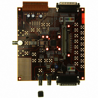
DK86060-3
Description
KIT DEV 16BIT DAC FOR MB86060
Manufacturer
Fujitsu Semiconductor America Inc
Specifications of DK86060-3
Number Of Dac's
1
Number Of Bits
16
Outputs And Type
1, Differential
Sampling Rate (per Second)
400M
Data Interface
Parallel
Dac Type
Current
Voltage Supply Source
Single
Operating Temperature
-40°C ~ 85°C
Utilized Ic / Part
MB86060
Lead Free Status / RoHS Status
Lead free / RoHS Compliant
Other names
865-1009


February 2009 Version 2.0
FME/MS/SFDAC1/DS/4250
MB86060 16-bit Interpolating Digital to Analog Converter
Another significant reason for splitting the digital data ground plane from the main digital ground is
that when using a remote data generator (e.g. a benchtop pattern or data generator) there is a
tendency for noise to be injected on the data ground by the equipment. This is significant because
the data rate is high, the data bus is wide, and it’s correlation with the signal can cause spurious tones
which degrade SFDR. The coupling mechanism is from the fast-slewing data inputs via the
capacitance of the input pins/pads/protection diodes into the internal circuits. The transient currents
through these parasitics can be several hundred milliamps. For this reason, it is recommended that
this region is not connected to the device star point but to the PSU star point directly.
The data supplies are only used for the input section of the device, so noise in this region cannot
couple into the DAC core. The digital supplies connect to the digital circuits (filters, noise shaper and
ditherer) inside the DAC, including those inside the DAC core. The control inputs can use this supply
because they toggle more slowly (if at all) and aren't correlated with the data. The analog sections
(Analog, Clock and Reference) have separate supply connections as transition dependant currents
from the digital sections will cause delay modulation in the clock path, and amplitude modulation in
the analog output section.
Each supply should be decoupled, producing a low impedance shunt at high frequency. The Digital,
Analog, Clock and Reference sections can be connected directly to the device star point, but
preferably through a small inductor. If a fully split power (VDD) plane is not desired, then as a
minimum only the ground plane need be split as described. However it is very important to isolate the
I/O supply (DVDD) from all other supplies in some way, possibly feeding the supply through a low-R
resistor or ferrite bead. This will help to filter out noise.
If the data (signal) and control lines are connected to the same device (e.g. an ASIC or FPGA), then
generally this should have been designed to support separate supply and ground pins for the digital
data bus. The ground plane at the generating device (ASIC or FPGA) then becomes the star point
for the data, requiring cuts in the ground/supply planes on either side of the data bus, and looping
under the DAC. The digital data decoupling at the DAC should also be inside this loop. This gives a
"U" shaped cut in the planes with the open end at the data source (with decoupling) and the closed
end at the DAC (with decoupling). All the data return currents will then be confined inside this "U",
and so none of them can couple into the analog ground planes to degrade SFDR. It may be advisable
to bury the digital data bus tracks on an internal layer, with data ground planes above, below and
either side of the tracks (the ground layers connected together with a “picket fence” row of vias) to
shield against RF radiation.
Figure 12 shows these principles applied to the ground plane of an application board. The pad on the
left represents the PSU star point, and the pad in the center represents the device star point. These
points could be realized with a via, so that the connection from the PSU out to other star points could
be made on another layer if necessary. The positioning of the plane breaks are also shown. The
breaks in the planes between each section should mark the boundary of that section. It is very
important to ensure that there are no tracks crossing these boundaries, or any splits in the planes
that tracks must cross, as this will create current loops within the plane itself.
The power supply track region is shown extending to the side of the device for reference purposes.
If the PSU region is not required, then the region should be merged with the Digital region.
Page 22 of 44
Production
Copyright © 2003-2009 Fujitsu Microelectronics Europe GmbH
Disclaimer: The contents of this document are subject to change without notice. Customers are advised to consult with FUJITSU sales representatives before
ordering.The information and circuit diagrams in this document are presented “as is”, no license is granted by implication or otherwise.
Related parts for DK86060-3
Image
Part Number
Description
Manufacturer
Datasheet
Request
R

Part Number:
Description:
IC POWER SUPPLY MONITOR 8SOP
Manufacturer:
Fujitsu Semiconductor America Inc
Datasheet:
Part Number:
Description:
IC POWER SUPPLY MONITOR 8SOP
Manufacturer:
Fujitsu Semiconductor America Inc
Datasheet:

Part Number:
Description:
IC MCU 60K FLASH 2KB RAM 52LQFP
Manufacturer:
Fujitsu Semiconductor America Inc
Datasheet:

Part Number:
Description:
IC MCU 32BIT 256KB FLASH 120LQFP
Manufacturer:
Fujitsu Semiconductor America Inc
Datasheet:
Part Number:
Description:
IC CTLR TOUCH SENSOR 12CH 30SSOP
Manufacturer:
Fujitsu Semiconductor America Inc
Datasheet:

Part Number:
Description:
IC CTLR TOUCH SENSOR 12CH 40QFN
Manufacturer:
Fujitsu Semiconductor America Inc
Datasheet:
Part Number:
Description:
SYNTHESIZER PLL DUAL INP 20SSOP
Manufacturer:
Fujitsu Semiconductor America Inc
Datasheet:

Part Number:
Description:
SYNTHESZR PLL 1.1GHZ DUAL 16SSOP
Manufacturer:
Fujitsu Semiconductor America Inc
Datasheet:

Part Number:
Description:
IC SSCG EMI RED 8-SOIC
Manufacturer:
Fujitsu Semiconductor America Inc
Datasheet:

Part Number:
Description:
IC SSCG EMI RED 8-TSSOP
Manufacturer:
Fujitsu Semiconductor America Inc
Datasheet:

Part Number:
Description:
IC SSCG EMI RED 8-SOP
Manufacturer:
Fujitsu Semiconductor America Inc
Datasheet:

Part Number:
Description:
SYNTHESIZER PLL 2.5GHZ 16SSOP
Manufacturer:
Fujitsu Semiconductor America Inc
Datasheet:
Part Number:
Description:
SYNTHESIZER PLL 1.2GHZ 16SSOP
Manufacturer:
Fujitsu Semiconductor America Inc
Datasheet:

Part Number:
Description:
SYNTHESIZER PLL 2.5GHZ 16BCC
Manufacturer:
Fujitsu Semiconductor America Inc
Datasheet:

Part Number:
Description:
IC SSCG EMI RED 8-SOP
Manufacturer:
Fujitsu Semiconductor America Inc
Datasheet: