STEVAL-ILL010V1 STMicroelectronics, STEVAL-ILL010V1 Datasheet

BOARD EVAL BASED ON L6902

STEVAL-ILL010V1

Manufacturer Part Number
STEVAL-ILL010V1
Description
BOARD EVAL BASED ON L6902
Manufacturer
STMicroelectronics
Datasheets

Specifications of STEVAL-ILL010V1

Mfg Application Notes
L6902D AppNote
Design Resources
STEVAL-ILL010V1 Gerber Files STEVAL-ILL010V1 Schematic STEVAL-ILL010V1 Bill of Materials
Current - Output / Channel
350mA
Outputs And Type
1, Non-Isolated
Voltage - Output
20 V
Features
Dimmable
Voltage - Input
8 ~ 30V
Utilized Ic / Part
L6902
Description/function
LED Driver Evaluation Module
Product
Display Modules
Core Chip
L6902
Dimming Control Type
PWM / Analog
Development Tool Type
Hardware - Eval/Demo Board
Mcu Supported Families
L6902
Supported Devices
L6902
Rohs Compliant
Yes
Lead Free Status / RoHS Status
Lead free / RoHS Compliant
For Use With/related Products
L6902
Other names
497-6411
STEVAL-ILL010V1
Features
Description
Thanks to their high efficiency and reliability,
super high-brightness LEDs are becoming more
and more popular as a subsitute for conventional
light sources. Although LEDs can be supplied
directly from a simple voltage source (like a
battery with resistor), for most applications it is
better to use a switching current source to
achieve not only higher efficiency but also better
light output.
This evaluation board is designed around an
L6902D-based DC-DC converter with dimming
interface. It board implements both of two well
known dimming methods:
While there is only a single dimming input
connector on the board, it can be used for both
dimming methods.
A signal between 0 and 3.3 V should be used for
analog (peak current) dimming. When the
dimming pin is grounded (0 V), the 350 mA
maximum output current is provided. Likewise,
when 3.3 V is applied to the pin, the current
provided is zero and the LED is off.
February 2008
For further information contact your local STMicroelectronics sales office.
Input voltage V
Dimming interface
Analog current control
Average current control by PWM
Analog current control
Average current control by PWM
in
= 8 V to 30 Vdc
High intensity LED dimming driver evaluation board
Rev 1
The second dimming method implemented on this
board is PWM control of average LED current.
This control requires a digital PWM signal (with an
amplitude of either 3.3 V or 5 V) between the
dimming pin and the ground pin. Varying the duty-
cycle on the board will then change the brightness
of the LED (100% = LED off, and 0% = LED fully
on).
STEVAL-ILL010V1
STEVAL-ILL010V1
based on the L6902
Data Brief
www.st.com
1/4
4

Related parts for STEVAL-ILL010V1

STEVAL-ILL010V1 Summary of contents

Page 1

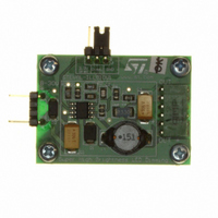
... LED is off. February 2008 For further information contact your local STMicroelectronics sales office. STEVAL-ILL010V1 based on the L6902 STEVAL-ILL010V1 The second dimming method implemented on this board is PWM control of average LED current. This control requires a digital PWM signal (with an amplitude of either 3 between the dimming pin and the ground pin ...

Page 2

... Circuit schematic 1 Circuit schematic Figure 1. Schematic 2/4 VREF 6 GND 7 STEVAL-ILL010V1 ...

Page 3

... STEVAL-ILL010V1 2 Revision history Table 1. Document revision history Date 11-Feb-2008 Revision 1 Initial release. Revision history Changes 3/4 ...

Page 4

... Australia - Belgium - Brazil - Canada - China - Czech Republic - Finland - France - Germany - Hong Kong - India - Israel - Italy - Japan - Malaysia - Malta - Morocco - Singapore - Spain - Sweden - Switzerland - United Kingdom - United States of America 4/4 Please Read Carefully: © 2008 STMicroelectronics - All rights reserved STMicroelectronics group of companies www.st.com STEVAL-ILL010V1 ...

Related keywords