DM300019 Microchip Technology, DM300019 Datasheet
DM300019
Specifications of DM300019
Available stocks


Related parts for DM300019

DM300019 Summary of contents
Page 1
... Starter Development Board © 2006 Microchip Technology Inc. dsPICDEM™ 80-Pin User’s Guide DS51584B ...
Page 2
... PowerMate, PowerTool, REAL ICE, rfLAB, rfPICDEM, Select Mode, Smart Serial, SmartTel, Total Endurance, UNI/O, WiperLock and ZENA are trademarks of Microchip Technology Incorporated in the U.S.A. and other countries. SQTP is a service mark of Microchip Technology Incorporated in the U.S.A. All other trademarks mentioned herein are property of their respective companies. ...
Page 3
... Introduction ................................................................................................... 25 3.2 Highlights ...................................................................................................... 25 3.3 Demonstration Program Summary ............................................................... 25 3.4 Demonstration Code Operation .................................................................... 27 3.5 Board Self-Test ............................................................................................ 30 Chapter 4. dsPICDEM™ Development Board Hardware 4.1 Hardware Overview ...................................................................................... 33 © 2006 Microchip Technology Inc. dsPICDEM DEVELOPMENT BOARD USER’S GUIDE Table of Contents ™ 80-PIN STARTER DS51584B-page iii ...
Page 4
... Starter Development Board User’s Guide Appendix A. Drawings and Schematics A.1 dsPICDEM 80-Pin Starter Development Board Layout ............................... 37 A.2 dsPICDEM 80-Pin Starter Development Board Schematic ......................... 38 Index .............................................................................................................................43 Worldwide Sales and Service .....................................................................................46 DS51584B-page iv © 2006 Microchip Technology Inc. ...
Page 5
... Chapter 4: dsPICDEM™ Development Board Hardware – This chapter describes the hardware comprising the dsPICDEM 80-Pin Starter Development Board. • Appendix A: Hardware Schematics – This appendix provides dsPICDEM 80-Pin Starter Development Board hardware layout and schematic diagrams. © 2006 Microchip Technology Inc. dsPICDEM DEVELOPMENT BOARD USER’S GUIDE Preface NOTICE TO CUSTOMERS ™ ...
Page 6
... Optional arguments mcc18 [options] file [options] Choice of mutually exclusive errorlevel {0|1} arguments selection Replaces repeated text var_name [, var_name...] Represents code supplied by void main (void) user { ... } © 2006 Microchip Technology Inc. Examples ® IDE User’s Guide ...
Page 7
... Consult this document for detailed information on the PIC24H 16-bit MCU family. Reference information found in this data sheet includes: • Device memory map • Device pinout and packaging details • Device electrical specifications • Overview of peripherals included in the device © 2006 Microchip Technology Inc. Preface ® DSC families. DS51584B-page 3 ...
Page 8
... Overview of peripherals included in the device ® MPLAB ASM30, MPLAB This document details Microchip Technology’s language tools for dsPIC DSC devices based on GNU technology. The language tools discussed are: • MPLAB ASM30 Assembler • MPLAB LINK30 Linker • MPLAB LIB30 Archiver/Librarian • ...
Page 9
... MPLAB IDE, MPLAB SIM simulator, MPLAB IDE Project Manager and general editing and debugging features. • Programmers – The latest information on Microchip programmers. These include the MPLAB PM3 and PRO MATE Plus and PICkit © 2006 Microchip Technology Inc. ® II device programmers and the PICSTART ™ 1 development programmers. ...
Page 10
... Technical support is available through the web site at: http://support.microchip.com DOCUMENT REVISION HISTORY Revision A (October 2005) • Initial Release of this Document. Revision B (March 2006) • Updated document to include dsPIC33F Digital Signal Controllers, and PIC24F and PIC24H MCU information. DS51584B-page 6 © 2006 Microchip Technology Inc. ...
Page 11
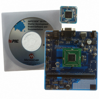
... Emulation Header on the dsPICDEM 80-Pin Starter Development Board (see Figure 1-2). • dsPICDEM 80-Pin Starter Development Board CD-ROM containing various demonstration programs provided by Microchip. © 2006 Microchip Technology Inc. dsPICDEM DEVELOPMENT BOARD USER’S GUIDE ™ 80-PIN STARTER ...
Page 12
... Starter Development Board User’s Guide FIGURE 1-1: FIGURE 1-2: For information on the components used on the dsPICDEM 80-Pin Starter Development Board see Chapter 4. “dsPICDEM™ Development Board Hardware”. DS51584B-page 8 dsPICDEM™ 80-PIN STARTER DEVELOPMENT BOARD TYPICAL PLUG-IN MODULE (PIM) © 2006 Microchip Technology Inc. ...
Page 13
... Demonstrates digital-to-analog conversion by generating an audio tone on LINE OUT. • Demonstrates analog-to-digital conversion by adjusting Potentiometer RP2 and transmitting the resulting digital value to the HyperTerminal on a PC. Refer to Chapter 3. “Demonstration Program Operation” for details on the demonstration code operation. © 2006 Microchip Technology Inc. Introduction DS51584B-page 9 ...
Page 14
... You can obtain these reference documents from your nearest Microchip sales office (listed in the back of this document downloading them from the Microchip web site (www.microchip.com). DS51584B-page 10 ® LINK30 and Utilities User’s Guide” (DS51317) ® ICD 2” poster (DS51265) © 2006 Microchip Technology Inc. ...
Page 15
... The following tutorial instructions assume the use of the dsPIC30F6014A device, which is supplied with the dsPICDEM 80-Pin Starter Development Board. However, this information applies to any of the dsPIC30F, dsPIC33F, PIC24F and PIC24H devices supported by the board. © 2006 Microchip Technology Inc. dsPICDEM DEVELOPMENT BOARD USER’S GUIDE Chapter 2. Tutorial ™ ...
Page 16
... From the Welcome screen, click Next to display the Project Wizard Step One dialog (see Figure 2-1). FIGURE 2-1: 5. From the Device: pull-down list, select dsPIC30F6014A and click Next >. The Project Wizard Step Two dialog displays as shown in Figure 2-2. DS51584B-page 12 PROJECT WIZARD, STEP 1, SELECT A DEVICE © 2006 Microchip Technology Inc. ...
Page 17
... Note: If you have the MPLAB C30 Toolsuite installed, browse to the C:\program files\microchip\MPLAB C30\bin\ location. 5. Click Next > to continue. The Project Wizard Step Three dialog displays (see Figure 2-3). © 2006 Microchip Technology Inc. PROJECT WIZARD, STEP 2, SELECT LANGUAGE TOOLSUITE Tutorial DS51584B-page 13 ...
Page 18
... Click Browse... and navigate to C:\Tutorial to place your project in the Tutorial folder. 3. Click Next > to continue. The Project Wizard Step Four dialog displays (see Figure 2-4). FIGURE 2-4: DS51584B-page 14 PROJECT WIZARD, STEP 3, NAME YOUR PROJECT PROJECT WIZARD, STEP 4, ADD FILES TO PROJECT © 2006 Microchip Technology Inc. ...
Page 19
... MyProject.mcp is the project file. Double click the Eg1_BlinkLed.s file in the project window to open the file. MPLAB IDE should now look similar to Figure 2-6. FIGURE 2-6: Project Window Output Window © 2006 Microchip Technology Inc. PROJECT WINDOW ® MPLAB IDE WORKSPACE Tutorial Source Code ...
Page 20
... Special Function Register (SFR) labels already defined for convenience. To build the code, select Build Options>Project from the Project menu. The Build Options dialog displays (see Figure 2-7). FIGURE 2-7: DS51584B-page 16 BUILD OPTIONS Browse to the location of the Assembler Include file © 2006 Microchip Technology Inc. ...
Page 21
... Check Link for ICD 2. 2. Click OK. The text box closes while the linker reserves space for the debug code used by the MPLAB ICD 2. 3. Click OK again to save these changes. The project is now ready to build. © 2006 Microchip Technology Inc. ® MPLAB LINK30 BUILD OPTIONS ...
Page 22
... From the Project menu, select Make. The Build Output window displays. 2. Observe the progress of the build. 3. When the BUILD SUCCEEDED message displays (see Figure 2-9), you are ready to program the device. FIGURE 2-9: DS51584B-page 18 BUILD OUTPUT © 2006 Microchip Technology Inc. ...
Page 23
... Operating a dsPIC33F device at 5.0V will cause a catastrophic failure of the device dsPIC30F device is being used, J5 can be open or closed. You will get 3.3V or 5.0V voltage to the V 3. Apply power to the board. © 2006 Microchip Technology Inc. XT w/PLL 4x Disabled CONFIGURATION SETTINGS CAUTION pin ...
Page 24
... MPLAB ICD 2 is being used with a dsPIC30F device. Allow so. If any errors are shown, double click the error message to get more information. FIGURE 2-12: DS51584B-page 20 ® TYPICAL dsPIC DSC DEVELOPMENT BOARD CONNECTED ® TO MPLAB ICD 2 ® ENABLING MPLAB ICD 2 Status indicates device is found © 2006 Microchip Technology Inc. ...
Page 25
... Observe the results of the programming. When “MPLAB ICD 2 Ready” displays, the device is programmed and ready to run. FIGURE 2-13: 3. Use the Debugger>Run menu to run the code. LED1 should start blinking when S1 is pressed. © 2006 Microchip Technology Inc. ® PROGRAMMING THE dsPIC DSC DEVICE Tutorial ...
Page 26
... The linker also provides values for the __SP_init and __SPLIM_init constants to initialize the Stack Pointer (W15) since the linker determines what RAM is available for the stack. DS51584B-page 22 PROGRAM MEMORY WINDOW CODE START-UP mov #__SP_init, W15 Pointer mov #__SPLIM_init, W0 mov W0, SPLIM © 2006 Microchip Technology Inc. ...
Page 27
... Press <F7> a few times and watch the RCOUNT value decrement (see Figure 2-16). RCOUNT is the repeat loop counter and decrements to zero as the instruction in a repeat loop is executed several times. FIGURE 2-16: © 2006 Microchip Technology Inc. SOURCE CODE WINDOW WATCH WINDOW DISPLAY Tutorial ...
Page 28
... View the code execution in program memory and source code • View registers in a Watch window • Set a breakpoint and make the code halt at a chosen location • Use the function keys to Reset, Run, Halt and Single Step the code DS51584B-page 24 btss PORTA,#S1 SETTING BREAKPOINT © 2006 Microchip Technology Inc. ...
Page 29
... LED RD4 blinks rate (once per second) until switch S1 is pressed again. Similarly, when switch S2 is pressed, LED RD5 blinks until switch S2 is pressed again. Timer 1 is set up to interrupt every half second. © 2006 Microchip Technology Inc. dsPICDEM™ 80-PIN STARTER DEVELOPMENT BOARD USER’S GUIDE ...
Page 30
... Mapping of data memory to program memory with PSV addressing • Initialization of the SPI port • Loading and transmission of data using hardware SPI To observe this demonstration, connect an oscilloscope probe to pin (the LINE OUT pin). DS51584B-page 26 ® is connected to the serial © 2006 Microchip Technology Inc. ...
Page 31
... LED1on is true, the LED labeled RD4 is toggled on and off every 0.5 seconds, causing the LED to blink. If LED1on is not true, the LED remains off. This demo program is illustrated in Figure 3-1. FIGURE 3-1: © 2006 Microchip Technology Inc. Demonstration Program Operation INTERRUPT PROCESSING FLOW DIAGRAM START INIT TIMER 1 For 0 ...
Page 32
... Buffer Full? Yes No Buffer Full? Yes No Buffer Full? Yes No Buffer Full? CR Yes No Buffer Full? LF Load Digit 3 into Transmit Buffer Load Digit 2 into Transmit Buffer Load Digit 1 into Transmit Buffer Load CR into Transmit Buffer Load Transmit Buffer © 2006 Microchip Technology Inc. ...
Page 33
... FIGURE 3-3: Set Reg W2 to Start of Tone Table Set Reg W3 to End of Tone Table Set Reg © 2006 Microchip Technology Inc. Demonstration Program Operation DIGITAL-TO-ANALOG CONVERSION PROGRAM FLOW START INIT SPI2 Set W4 = Value Pointed Using PSV ...
Page 34
... Op Amp circuit to the ADC of the dsPIC DSC device. The sine wave is analyzed to determine if a smooth sine wave has been generated. If all works well, the test passes. If there is a fault in the op amp or digital potentiometer, then this test fails. ® DSC, then © 2006 Microchip Technology Inc. ...
Page 35
... Blinking LED RD4 RD5 RD6 RD7 If all tests passed, then none of the LEDs will blink. © 2006 Microchip Technology Inc. Demonstration Program Operation Test Failed UART UART driver chip failed; UART shorting jumper not connected on J1 Keypad ...
Page 36
... Starter Development Board User’s Guide NOTES: DS51584B-page 32 © 2006 Microchip Technology Inc. ...
Page 37
... External Oscillator Socket (Section 4.1.12) ® 10 dsPIC DSC/PIC24 Device Header (Section 4.1.8) 11 Prototyping Area (Section 4.1.14) 12 Factory Test Socket © 2006 Microchip Technology Inc. dsPICDEM™ 80-PIN STARTER DEVELOPMENT BOARD USER’S GUIDE dsPICDEM™ 80-PIN STARTER DEVELOPMENT BOARD dsPICDEM™ 80-PIN STARTER DEVELOPMENT BOARD ...
Page 38
... I/O Port Header Header two-row header with appropriate labels for I/O ports. This header allows the user to easily probe appropriate I/O lines. DS51584B-page 34 through 4.7K resistors. Pressing the switch DD © 2006 Microchip Technology Inc. DD ...
Page 39
... Figure A-6. • LINE_OUT – Output signal from digital potentiometer • LINE_IN – Input signal for ADC 4.1.17 9 VDC Input Jack (J2) An input jack for 9V external power supply. © 2006 Microchip Technology Inc. dsPICDEM™ Development Board Hardware and the DD DD ...
Page 40
... Starter Development Board User’s Guide FIGURE 4-2: Align Corners of PIM and Header P1 DS51584B-page 36 ADAPTER BOARD PLUGS INTO HEADER ON MAIN BOARD Plug-in Module (PIM) © 2006 Microchip Technology Inc. ...
Page 41
... STARTER DEVELOPMENT BOARD LAYOUT Figure A-1 shows the parts layout for the dsPICDEM 80-Pin Starter Development Board. FIGURE A-1: © 2006 Microchip Technology Inc. dsPICDEM™ 80-PIN STARTER DEVELOPMENT BOARD USER’S GUIDE dsPICDEM™ 80-PIN STARTER DEVELOPMENT BOARD ...
Page 42
... RD3 RD12 RD13 RD4 RD5 RD6 RD7 RF0 RF1 RG1 RG0 RA6 RA7 RG14 RG12 RG13 DS51584B-page 38 RF5 RF4 RD15 RD14 RB15 RB14 RB13 RB12 RB11 RB10 RB9 RB8 SS AV +5VAN AV DD RA10 RA9 RB7 RB6 © 2006 Microchip Technology Inc. ...
Page 43
... FIGURE A-3: dsPICDEM™ 80-PIN STARTER DEVELOPMENT BOARD SCHEMATIC (SHEET μ © 2006 Microchip Technology Inc. Drawings and Schematics DS51584B-page 39 ...
Page 44
... Starter Development Board User’s Guide FIGURE A-4: dsPICDEM™ 80-PIN STARTER DEVELOPMENT BOARD SCHEMATIC (SHEET μ DS51584B-page 40 μ μ μ μ μ © 2006 Microchip Technology Inc. ...
Page 45
... RD12 RD13 RD4 RD5 RD6 RD7 GND DD V RF0 RF1 RG1 RG0 RA6 RA7 RG14 RG12 RG13 © 2006 Microchip Technology Inc. Drawings and Schematics RF5 RF4 RD15 RD14 RB15 RB14 RB13 RB12 DD V GND RB11 RB10 RB9 RB8 AGND +5VAN ...
Page 46
... Starter Development Board User’s Guide FIGURE A-6: dsPICDEM™ 80-PIN STARTER DEVELOPMENT BOARD SCHEMATIC (SHEET DS51584B-page 42 © 2006 Microchip Technology Inc. ...
Page 47
... Serial Communication Channels......................... 9 Development Board Layout ..................................... 37 Development Board Power ........................................ 9 Development Board Schematic...........................38 Device Clocking ......................................................... 9 Device Header ......................................................... 34 Digital Potentiometer................................................ 34 Documentation Conventions ........................................................ 2 Layout ................................................................. 1 © 2006 Microchip Technology Inc. dsPICDEM DEVELOPMENT BOARD USER’S GUIDE Index F Flow Diagram Analog-to-Digital Conversion ............................ 28 Interrupt Processing.......................................... 27 Free Software Foundation.......................................... 4 G GNU language tools ...
Page 48
... Starter Development Board User’s Guide R Reading, Recommended............................................ 3 Readme...................................................................... 3 Reference Documents.............................................. 10 Reset Switch ............................................................ 35 RS-232 Serial Port ................................................... 34 S Sample Device ......................................................... 35 Schematics......................................................... 38 Serial Communication Channel.................................. 9 W Warranty Registration................................................. 3 Watch window .......................................................... 23 Workspace ............................................................... 12 WWW Address ........................................................... 5 DS51584B-page 44 42 – © 2006 Microchip Technology Inc. ...
Page 49
... NOTES: © 2006 Microchip Technology Inc. Index DS51584B-page 45 ...
Page 50
... Fax: 886-3-572-6459 Taiwan - Kaohsiung Tel: 886-7-536-4818 Fax: 886-7-536-4803 Taiwan - Taipei Tel: 886-2-2500-6610 Fax: 886-2-2508-0102 Thailand - Bangkok Tel: 66-2-694-1351 Fax: 66-2-694-1350 © 2006 Microchip Technology Inc. EUROPE Austria - Wels Tel: 43-7242-2244-399 Fax: 43-7242-2244-393 Denmark - Copenhagen Tel: 45-4450-2828 Fax: 45-4485-2829 France - Paris Tel: 33-1-69-53-63-20 ...