R0K561622S000BE Renesas Electronics America, R0K561622S000BE Datasheet - Page 702
R0K561622S000BE
Manufacturer Part Number
R0K561622S000BE
Description
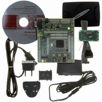
KIT STARTER FOR H8SX/1622
Manufacturer
Renesas Electronics America
Series
Renesas Starter Kits (RSK)r
Type
MCUr
Specifications of R0K561622S000BE
Contents
Board, Cables, CD, Debugger, Power Supply
Silicon Manufacturer
Renesas
Features
Coding And Debugging, E10A Emulator, RS232 Serial Connection
Kit Contents
Board
Silicon Family Name
H8SX/1622F
Silicon Core Number
R5F61622N50LGV
Lead Free Status / RoHS Status
Lead free / RoHS Compliant
For Use With/related Products
H8SX/1622
Lead Free Status / RoHS Status
Lead free / RoHS Compliant, Lead free / RoHS Compliant


Section 16 Serial Communication Interface (SCI)
At power-on and transitions to/from software standby mode, use the following procedure to secure
the appropriate clock duty cycle.
• At power-on
• At mode switching
Rev. 2.00 Sep. 16, 2009 Page 672 of 1036
REJ09B0414-0200
To secure the appropriate clock duty cycle simultaneously with power-on, use the following
procedure.
1. Initially, port input is enabled in the high-impedance state. To fix the potential level, use a
2. Fix the SCK pin to the specified output using the CKE1 bit in SCR.
3. Set SMR and SCMR to enable smart card interface mode.
At transition from smart card interface mode to software standby mode
At transition from smart card interface mode to software standby mode
pull-up or pull-down resistor.
Set the CKE0 bit in SCR to 1 to start clock output.
1. Set the data register (DR) and data direction register (DDR) corresponding to the SCK
2. Write 0 to the TE and RE bits in SCR to stop transmission/reception. Simultaneously,
3. Write 0 to the CKE0 bit in SCR to stop the clock.
4. Wait for one cycle of the serial clock. In the mean time, the clock output is fixed to the
5. Make the transition to software standby mode.
6. Clear software standby mode.
7. Write 1 to the CKE0 bit in SCR to start clock output. A clock signal with the
pin to the values for the output fixed state in software standby mode.
set the CKE1 bit to the value for the output fixed state in software standby mode.
specified level with the duty cycle retained.
appropriate duty cycle is then generated.
[1] [2] [3]
Normal operation
Figure 16.32 Clock Stop and Restart Procedure
[4] [5]
Software
standby
[6]
[7]
Normal operation
Related parts for R0K561622S000BE
Image
Part Number
Description
Manufacturer
Datasheet
Request
R

Part Number:
Description:
KIT STARTER FOR M16C/29
Manufacturer:
Renesas Electronics America
Datasheet:

Part Number:
Description:
KIT STARTER FOR R8C/2D
Manufacturer:
Renesas Electronics America
Datasheet:

Part Number:
Description:
R0K33062P STARTER KIT
Manufacturer:
Renesas Electronics America
Datasheet:

Part Number:
Description:
KIT STARTER FOR R8C/23 E8A
Manufacturer:
Renesas Electronics America
Datasheet:

Part Number:
Description:
KIT STARTER FOR R8C/25
Manufacturer:
Renesas Electronics America
Datasheet:

Part Number:
Description:
KIT STARTER H8S2456 SHARPE DSPLY
Manufacturer:
Renesas Electronics America
Datasheet:

Part Number:
Description:
KIT STARTER FOR R8C38C
Manufacturer:
Renesas Electronics America
Datasheet:

Part Number:
Description:
KIT STARTER FOR R8C35C
Manufacturer:
Renesas Electronics America
Datasheet:

Part Number:
Description:
KIT STARTER FOR R8CL3AC+LCD APPS
Manufacturer:
Renesas Electronics America
Datasheet:
Part Number:
Description:
KIT STARTER FOR RX610
Manufacturer:
Renesas Electronics America
Datasheet:

Part Number:
Description:
KIT STARTER FOR R32C/118
Manufacturer:
Renesas Electronics America
Datasheet:

Part Number:
Description:
KIT DEV RSK-R8C/26-29
Manufacturer:
Renesas Electronics America
Datasheet:

Part Number:
Description:
KIT STARTER FOR SH7124
Manufacturer:
Renesas Electronics America
Datasheet:

Part Number:
Description:
KIT DEV FOR SH7203
Manufacturer:
Renesas Electronics America
Datasheet:
Part Number:
Description:
KIT STARTER FOR R8C/18191A1B
Manufacturer:
Renesas Electronics America
Datasheet: