R0K561622S000BE Renesas Electronics America, R0K561622S000BE Datasheet - Page 783
R0K561622S000BE
Manufacturer Part Number
R0K561622S000BE
Description
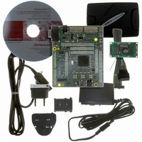
KIT STARTER FOR H8SX/1622
Manufacturer
Renesas Electronics America
Series
Renesas Starter Kits (RSK)r
Type
MCUr
Specifications of R0K561622S000BE
Contents
Board, Cables, CD, Debugger, Power Supply
Silicon Manufacturer
Renesas
Features
Coding And Debugging, E10A Emulator, RS232 Serial Connection
Kit Contents
Board
Silicon Family Name
H8SX/1622F
Silicon Core Number
R5F61622N50LGV
Lead Free Status / RoHS Status
Lead free / RoHS Compliant
For Use With/related Products
H8SX/1622
Lead Free Status / RoHS Status
Lead free / RoHS Compliant, Lead free / RoHS Compliant


19.4.1
When the ∆Σ A/D converter is to be used, register settings should be made in accord with the
procedure for activation given below.
Figure 19.2 shows the procedure for activating the ∆Σ A/D converter.
Set the TRGS1 and TRGS0 bits in DSADCSR
(ADIE, SCANE, CH5 to CH0, CKS, GAIN)
Clear the MSTPC14 bit in MSTPCRC to 0
Set the ACK2 to ACK0 bits in DSADMR
Set ADST = 1 to start A/D conversion
Set the bits in DSADCSR/DSADCR
Set the BIASE bit in DSADMR to 1
Set the DSE bit in DSADCR to 1
Procedure for Activating the ∆Σ A/D Converter
Figure 19.2 Procedure for Activating the ∆Σ A/D Converter
Start
[1]
[2]
[3]
[4]
[5]
[6]
[7]
[1]
[2]
[3]
[4]
[5]
[6]
[7]
Starts the biasing circuit.
To ensure stabilization of the circuit, a period of waiting is
necessary after the biasing circuit has started up and by the
time step [7] is executed. See section 19.6, Usage Notes, for
details. BIASE should be set while the ∆Σ A/D converter is in
the module stop state.
Sets a frequency-divided clock signal for the ∆Σ A/D
converter. When changing the clock-division setting, put the
∆Σ A/D converter in the module stop state.
Releases the ∆Σ A/D converter from the module stop state.
On release, supply of the Aφ clock and the Pφ clock
connected to the ∆Σ A/D converter start.
Starts the ∆Σ modulator.
The analog circuit starts to operate, consuming a certain
amount of power. The ∆Σ A/D converter enters the idle state.
Sets the operating mode of the ∆Σ A/D converter, selects
channels, etc.
Sets the trigger input for starting A/D conversion.
Leave the bits at the initial value if A/D conversion is to be
started by software.
A/D conversion starts when ADST is set to 1 by software or
by input of the trigger set in step [6].
Rev. 2.00 Sep. 16, 2009 Page 753 of 1036
Section 19 ∆Σ A/D Converter
REJ09B0414-0200
Related parts for R0K561622S000BE
Image
Part Number
Description
Manufacturer
Datasheet
Request
R

Part Number:
Description:
KIT STARTER FOR M16C/29
Manufacturer:
Renesas Electronics America
Datasheet:

Part Number:
Description:
KIT STARTER FOR R8C/2D
Manufacturer:
Renesas Electronics America
Datasheet:

Part Number:
Description:
R0K33062P STARTER KIT
Manufacturer:
Renesas Electronics America
Datasheet:

Part Number:
Description:
KIT STARTER FOR R8C/23 E8A
Manufacturer:
Renesas Electronics America
Datasheet:

Part Number:
Description:
KIT STARTER FOR R8C/25
Manufacturer:
Renesas Electronics America
Datasheet:

Part Number:
Description:
KIT STARTER H8S2456 SHARPE DSPLY
Manufacturer:
Renesas Electronics America
Datasheet:

Part Number:
Description:
KIT STARTER FOR R8C38C
Manufacturer:
Renesas Electronics America
Datasheet:

Part Number:
Description:
KIT STARTER FOR R8C35C
Manufacturer:
Renesas Electronics America
Datasheet:

Part Number:
Description:
KIT STARTER FOR R8CL3AC+LCD APPS
Manufacturer:
Renesas Electronics America
Datasheet:
Part Number:
Description:
KIT STARTER FOR RX610
Manufacturer:
Renesas Electronics America
Datasheet:

Part Number:
Description:
KIT STARTER FOR R32C/118
Manufacturer:
Renesas Electronics America
Datasheet:

Part Number:
Description:
KIT DEV RSK-R8C/26-29
Manufacturer:
Renesas Electronics America
Datasheet:

Part Number:
Description:
KIT STARTER FOR SH7124
Manufacturer:
Renesas Electronics America
Datasheet:

Part Number:
Description:
KIT DEV FOR SH7203
Manufacturer:
Renesas Electronics America
Datasheet:
Part Number:
Description:
KIT STARTER FOR R8C/18191A1B
Manufacturer:
Renesas Electronics America
Datasheet: