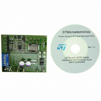
EVAL6730 STMicroelectronics, EVAL6730 Datasheet

EVAL6730
Specifications of EVAL6730
Available stocks
Related parts for EVAL6730
EVAL6730 Summary of contents
Page 1
... MHz positions dip-switch allows to select the UVLO threshold ( Bus), the OVP intervention mode and the sink-mode current capability. Demoboard picture January 2007 For further information contact your local STMicroelectronics sales office. L6730: 20A Demoboard Rev 1 EVAL6730 Data Brief ) but it SW 1/9 www.st.com ...
Page 2
... R6 S2 C13 R7 S3 R14 R10 S6 R11 S7 Manufacturer Neohm Neohm Neohm Neohm Neohm Neohm Neohm Neohm Neohm Neohm Neohm Neohm EVAL6730 C3 C4-C6 R18 HGATE L1 Q1-3 PHASE R19 R21 LGATE D2 C20 Q4-6 PGND PGOOD SS R20 C15 OSC VCCDR R17 STATE R16 A B R15 ...
Page 3
... EVAL6730 Table 1. Demoboard part list (continued) Reference Value R14 1 KΩ 1% 100mW R15 1 KΩ 1% 100mW R16 4.7 KΩ 1% 100mW R17 N.C. 2.2 Ω R18 2.2 Ω R19 R20 10 KΩ 1% 100 mW R21 N.C. R22 N.C. 0 Ω R23 C1 220 nF C3-C7-C9-C15-C21 100 ...
Page 4
... The output voltage is fixed at 3.3 V but it can be changed by replacing the resistor R14 of the output resistor divider: R ⎛ • -------- - ⎝ O REF R 4/9 Series Inductor value (µH) SPM12550T-1R0M220 FDA1254 HCF1305-1R0 HC5-1R0 Series Capacitor value(µF) C4532X5R1E156M C3225X5R0J107M 25PS100MJ12 ECJ4YB0J107M ⎞ 16 ⎠ 14 EVAL6730 Saturation current ( 2.2 14 1.15 22 1.3 27 Rated voltage ( 100 6.3 100 25 100 6.3 ...
Page 5
... EVAL6730 The over-current-protection limit is set but it can be changed by replacing the resistors R1 and R12 (see OCL and OCH pin). ● Vcc-Gndcc: Using the input voltage to supply the controller no power is required at this input. However the controller can be supplied separately from the power stage through the Vcc input (4.5- 14V) and, in this case, jumper G1 must be left open. ● ...
Page 6
... The following figures show the demoboard efficiency versus load current for different values of input voltage and switching frequency: Figure 3. Demoboard efficiency - Fsw=400 KHz Figure 4. Demoboard efficiency - Fsw=645 KHz 95.00% 90.00% 85.00% 80.00% 75.00% 70.00% 6/9 Fsw=400KHz 95.00% 90.00% Vin=5V 85.00% 80.00% Vin=12V 75.00 Iout (A) Fsw=645KHz Vin=5V Vin=12V Iout (A) EVAL6730 Vo=3. Vo=3. ...
Page 7
... EVAL6730 Figure 5. Demoboard efficiency - Fsw=1 MHz 95.00% 90.00% 85.00% 80.00% 75.00% 70.00% 65.00% 60.00% Figure 6. Efficiency with 2xSTS12NH3LL+2XSTSJ100NH3LL 0.96 0.95 0.94 0.93 0.92 0.91 0.9 0.89 0.88 0.87 Fsw=1MHz Iout (A) 12V-->3. OUTPUT CURRENT (A) Features Vo=3.3V Vin=5V Vin=12V 400KHz 700KHz 1MHz ...
Page 8
... Pictures of demoboard EVAL6730 2 Pictures of demoboard EVAL6730 PCB layout - top layer Figure 7. Figure 9. PCB layout - Signal-ground layer 3 Revision history Table 5. Revision history Date 03-Jan-2007 8/9 Figure 8. Figure 10. PCB layout - bottom layer Revision 1 First issue EVAL6730 PCB layout - power ground layer Changes ...
Page 9
... EVAL6730 Information in this document is provided solely in connection with ST products. STMicroelectronics NV and its subsidiaries (“ST”) reserve the right to make changes, corrections, modifications or improvements, to this document, and the products and services described herein at any time, without notice. All ST products are sold pursuant to ST’s terms and conditions of sale. ...


