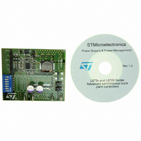
EVAL6730 STMicroelectronics, EVAL6730 Datasheet - Page 12

EVAL6730
Manufacturer Part Number
EVAL6730
Description
EVAL BOARD FOR L6730XX
Manufacturer
STMicroelectronics
Type
Motor / Motion Controllers & Driversr
Datasheets
1.L6730TR.pdf
(52 pages)
2.L6730DTR.pdf
(50 pages)
3.EVAL6730.pdf
(9 pages)
4.EVAL6732.pdf
(43 pages)
Specifications of EVAL6730
Main Purpose
DC/DC, Step Down
Outputs And Type
1, Non-Isolated
Power - Output
66W
Voltage - Output
3.3V
Current - Output
20A
Voltage - Input
4.5 ~ 14V
Regulator Topology
Buck
Frequency - Switching
400kHz
Board Type
Fully Populated
Utilized Ic / Part
L6730
Input Voltage
8 V to 52 V
Product
Power Management Modules
Lead Free Status / RoHS Status
Lead free / RoHS Compliant
For Use With/related Products
L6208
Other names
497-5501
Available stocks
Company
Part Number
Manufacturer
Quantity
Price
AN1451 APPLICATION NOTE
2.9 Input Logic pins
CW/CCW, CONTROL, RESET, HALF/FULL, CLOCK are CMOS/TTL compatible logic input pins. The input compar-
ator has been realized with hysteresis to ensure the required noise immunity. Typical values for turn-on and turn-off
thresholds are V
static discharge), and can be directly connected to the logic outputs of a µC; a series resistor is generally not recom-
mended, as it could help inducted noise to disturb the inputs. All logic pins enforce a specific behavior and cannot be
left unconnected.
Figure 10. Logic input pins.
2.10 EN pin
The EN pin is, actually, bi-directional: as an input, with a comparator similar to the other logic input pins (TTL/CMOS
with hysteresis), it controls the state of the PowerDMOS. When this pin is at a low logic level, all the PowerDMOS are
turned off. The EN pin is also connected to the open drain output of the protection circuit that will pull the pin to GND
if over current or over temperature conditions exist. For this reason, EN pin must be driven through a series resistor
of 2.2k minimum (for 5V logic), to allow the voltage at the pin to be pulled below the turn-off threshold.
A capacitor (C1 in Figure 5) connected between the EN pin and GND is also recommended, to reduce the r.m.s. value
of the output current when overcurrent conditions persist (see Over Current Protection section). EN pin must not be
left unconnected.
Figure 11. EN input pin.
12/43
th,ON
= 1.8V and V
th,OFF
= 1.3V. Pins are ESD protected (see Figure 10) (2kV human-body electro-
EN
RESET, CW/CCW
CONTROL,
HALF/FULL, CLOCK,
Protection
ESD
Protection
ESD
5 V
5 V


