EVAL6730 STMicroelectronics, EVAL6730 Datasheet - Page 25

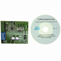
EVAL6730
Manufacturer Part Number
EVAL6730
Description
EVAL BOARD FOR L6730XX
Manufacturer
STMicroelectronics
Type
Motor / Motion Controllers & Driversr
Datasheets
1.L6730TR.pdf
(52 pages)
2.L6730DTR.pdf
(50 pages)
3.EVAL6730.pdf
(9 pages)
4.EVAL6732.pdf
(43 pages)
Specifications of EVAL6730
Main Purpose
DC/DC, Step Down
Outputs And Type
1, Non-Isolated
Power - Output
66W
Voltage - Output
3.3V
Current - Output
20A
Voltage - Input
4.5 ~ 14V
Regulator Topology
Buck
Frequency - Switching
400kHz
Board Type
Fully Populated
Utilized Ic / Part
L6730
Input Voltage
8 V to 52 V
Product
Power Management Modules
Lead Free Status / RoHS Status
Lead free / RoHS Compliant
For Use With/related Products
L6208
Other names
497-5501
Available stocks
Company
Part Number
Manufacturer
Quantity
Price
Figure 26. Thermal Data inputs and results.
2.14 Choosing the Decay Mode
L6208 can operate in either fast or slow decay mode, each having a specific recirculation path for the current
during off-time. In slow decay mode only the lower DMOS is turned off and the current recirculates around the
upper half of the bridge so that voltage across the coil is essentially 0. In Fast decay mode both DMOS are
turned off and the current recirculates back to the power supply rail so that voltage across the coil is essentially
power supply voltage itself.
Slow decay operation provides several advantages: for a given peak current and off-time, current ripple is min-
imized, and the same is true for acoustic noise and losses in the motor iron (achieving the same current ripple
with fast decay mode would require a shorter off-time resulting in a higher switching frequency and higher power
dissipation in the IC). As current recirculates in the upper half of the bridge and both the high side DMOS in the
same bridge are on, synchronous rectification is realized, minimizing power dissipation in the power switches.
Also, as no output pin goes below GND (see Supply Voltage Ratings and Operating Range section), no power
is dissipated on the sense resistor during the off-time (see Sensing Resistors section).
On the other hand, slow decay can be undesirable in some situations, for example when current has to be reg-
ulated at very low values or motor winding L / R ratio is high. In these cases an on-time shorter than the minimum
t
regulation (refer to the Programmable off-time Monostable section).
Another situation where fast decay is to be preferred to slow decay is with regulated current expected to vary
over time with a given profile (enforced providing a variable voltage on the V
section). Here fast decay helps following fast decreasing edges in the desired profile.
ON
(about 1.5µs) may be requested to regulate the current, and this can cause the PWM controller to loose the
Pins / Slug Tem perature
Junction to Pins / Slug
Am bient Tem perature
Estim ated Junction
Therm al Resistance
Therm al Resistance
Junction to Am bient
Copper Area is on
Ground Layer
Tem perature
Copper Area
Estim ated
Package
Sam e side of the device
Input Data
Results
122.66
103.60
SO24
53.36
14.00
N/A
4.0
50
AN1451 APPLICATION NOTE
ref
pins, see also Microstepping
-25 ÷ 100 ºC
1÷10 sq. cm
ºC / W
ºC / W
ºC
25/43


