EVAL6730 STMicroelectronics, EVAL6730 Datasheet - Page 28
EVAL6730
Manufacturer Part Number
EVAL6730
Description
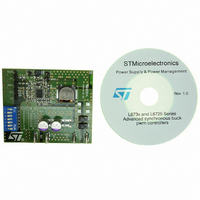
EVAL BOARD FOR L6730XX
Manufacturer
STMicroelectronics
Type
Motor / Motion Controllers & Driversr
Datasheets
1.L6730TR.pdf
(52 pages)
2.L6730DTR.pdf
(50 pages)
3.EVAL6730.pdf
(9 pages)
4.EVAL6732.pdf
(43 pages)
Specifications of EVAL6730
Main Purpose
DC/DC, Step Down
Outputs And Type
1, Non-Isolated
Power - Output
66W
Voltage - Output
3.3V
Current - Output
20A
Voltage - Input
4.5 ~ 14V
Regulator Topology
Buck
Frequency - Switching
400kHz
Board Type
Fully Populated
Utilized Ic / Part
L6730
Input Voltage
8 V to 52 V
Product
Power Management Modules
Lead Free Status / RoHS Status
Lead free / RoHS Compliant
For Use With/related Products
L6208
Other names
497-5501
Available stocks
Company
Part Number
Manufacturer
Quantity
Price


Device description
5.11
28/52
Table 7
Figure 23. External resistor
Table 7.
Synchronization
The presence of many converters on the same board can generate beating frequency noise.
To avoid this it is important to make them operate at the same switching frequency.
Moreover, a phase shift between different modules helps to minimize the RMS current on
the common input capacitors.
synchronization. Two or more devices can be synchronized simply connecting together the
SYNCH pins. The device with the higher switching frequency will be the Master while the
other one will be the slave. The slave controller will increase its switching frequency
reducing the ramp amplitude proportionally and then the modulator gain will be increased.
To avoid a huge variation of the modulator gain, the best way to synchronize two or more
devices is to make them work at the same switching frequency and, in any case, the
switching frequencies can differ for a maximum of 50% of the lowest one. If, during
synchronization between two (or more) L6730, it’s important to know in advance which the
master is, it’s timely to set its switching frequency at least 15% higher than the slave. Using
an external clock signal (f
different switching frequency (f
6.2KΩ
4.3KΩ
2.7KΩ
1.8KΩ
1.2KΩ
11KΩ
N.C
0Ω
R1
shows how to set the different options through an external resistor divider:
S/O/U and CC/O/U pin
2.7KΩ
2.7KΩ
2.7KΩ
2.7KΩ
2.7KΩ
2.7KΩ
N.C
R2
0Ω
EXT
) to synchronize one or more devices that are working at a
Figure 24
R2
Doc ID 11938 Rev 3
SW
R1
V
) it is recommended to follow the below formula:
SOU
f
SW
0.2
0.3
0.4
0.5
0.6
0.7
/V
0
1
≤
CCDR
shows the results of two modules in
f
EXT
≤
CC/O/U
VCCDR
S/O/U
1
12V BUS
12V BUS
12V BUS
12V BUS
5V BUS
5V BUS
5V BUS
5V BUS
3 ,
UVLO
⋅
L6730/B
f
SW
Not latched
Not latched
Not latched
Not latched
Latched
Latched
Latched
Latched
OVP
L6730 - L6730B
SINK CC
Not
Yes
Not
Yes
Not
Yes
Not
Yes
Related parts for EVAL6730
Image
Part Number
Description
Manufacturer
Datasheet
Request
R

Part Number:
Description:
STMicroelectronics [RIPPLE-CARRY BINARY COUNTER/DIVIDERS]
Manufacturer:
STMicroelectronics
Datasheet:
Part Number:
Description:
STMicroelectronics [LIQUID-CRYSTAL DISPLAY DRIVERS]
Manufacturer:
STMicroelectronics
Datasheet:

Part Number:
Description:
BOARD EVAL FOR MEMS SENSORS
Manufacturer:
STMicroelectronics
Datasheet:
Part Number:
Description:
NPN TRANSISTOR POWER MODULE
Manufacturer:
STMicroelectronics
Datasheet:
Part Number:
Description:
TURBOSWITCH ULTRA-FAST HIGH VOLTAGE DIODE
Manufacturer:
STMicroelectronics
Datasheet:
Part Number:
Description:
Manufacturer:
STMicroelectronics
Datasheet:
Part Number:
Description:
DIODE / SCR MODULE
Manufacturer:
STMicroelectronics
Datasheet:
Part Number:
Description:
DIODE / SCR MODULE
Manufacturer:
STMicroelectronics
Datasheet:
Part Number:
Description:
Search -----> STE16N100
Manufacturer:
STMicroelectronics
Datasheet:
Part Number:
Description:
Search ---> STE53NA50
Manufacturer:
STMicroelectronics
Datasheet:
Part Number:
Description:
NPN Transistor Power Module
Manufacturer:
STMicroelectronics
Datasheet:
Part Number:
Description:
DIODE / SCR MODULE
Manufacturer:
STMicroelectronics
Datasheet: