TK1-L2-12V Panasonic Electric Works, TK1-L2-12V Datasheet - Page 3
TK1-L2-12V
Manufacturer Part Number
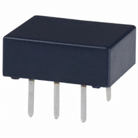
TK1-L2-12V
Description
RELAY LATCH LOPRO 2A 12VDC PCB
Manufacturer
Panasonic Electric Works
Series
TKr
Datasheet
1.TK1-5V.pdf
(6 pages)
Specifications of TK1-L2-12V
Relay Type
General Purpose
Circuit
SPDT (1 Form C)
Contact Rating @ Voltage
2A @ 30VDC
Coil Type
Latching, Dual Coil
Coil Current
20.8mA
Coil Voltage
12VDC
Control On Voltage (max)
9 VDC
Mounting Type
Through Hole
Termination Style
PC Pin
Lead Free Status / RoHS Status
Lead free / RoHS Compliant
Control Off Voltage (min)
-
Other names
255-1760
255-1760-5
255-1760
255-1760-5
255-1760
Available stocks
Company
Part Number
Manufacturer
Quantity
Price
Company:

Part Number:
TK1-L2-12V
Manufacturer:
Panasonic
Quantity:
12 000


3) 2 coil latching
*Pulse drive (JIS C 5442-1986)
2. Specifications
Notes: *1 This value can change due to the switching frequency, environmental conditions, and desired reliability level, therefore it is recommended to check this with the
Contact
Rating
Electrical
characteristics
Mechanical
characteristics
Expected life
Conditions
Unit weight
Nominal coil
Characteristics
1.5V DC
4.5V DC
12V DC
24V DC
voltage
3V DC
5V DC
6V DC
9V DC
*2 Refer to 6. Conditions for operation, transport and storage mentioned in AMBIENT ENVIRONMENT.
*3 The maximum ambient temperature allows for coil temperature rise at maximum allowable coil voltage.
actual load. (SX relays are available for low level load switching [10V DC, 10mA max. level])
As for the applicable range of continuous carrying current against temperature, please refer to “Maximum value of continuous carrying current” chart. (Page 98)
nominal voltage*
75%V or less of
(at 20 C
Arrangement
Initial contact resistance, max.
Contact material
Nominal switching capacity
Max. switching power
Max. switching voltage
Max. switching current
Min. switching capacity (Reference value)*
Nominal operating
power
Insulation resistance (Initial)
Breakdown voltage
(Initial)
Surge breakdown
voltage (Initial)
Temperature rise (at 20 C
Operate time [Set time] (at 20 C
Release time [Reset time] (at 20 C
Shock resistance
Vibration resistance
Mechanical
Electrical
Conditions for operation, transport and storage*
Max. operating speed (at rated load)
Set voltage
(Initial)
68
F)
All Rights Reserved © COPYRIGHT Panasonic Electric Works Co., Ltd.
Single side stable
1 coil latching
2 coil latching
Between open contacts
Between contact and coil
Between open contacts
Between contacts and coil
Functional
Destructive
Functional
Destructive
nominal voltage*
75%V or less of
Item
(at 20 C
Reset voltage
68
(Initial)
F)
68
68
68
F)
F)
F)
1
[ 10%] (at 20 C
133.9mA
66.7mA
44.5mA
33.3mA
22.2mA
20.8mA
16.7mA
Set coil
2
40mA
Nominal operating
current
1 Form C
Max. 50 m (By voltage drop 6 V DC 1A)
Ag+Au clad
2 A 30 V DC (resistive load)
60 W (DC) (resistive load)
220 V DC
2 A
10 A 10mV DC
140 mW (1.5 to 12 V DC), 270 mW (24 V DC)
100 mW (1.5 to 12 V DC), 150 mW (24 V DC)
200 mW (1.5 to 9 V DC), 250 mW (12 V DC), 400 mW (24 V DC)
Min. 1,000M
Measurement at same location as “Initial breakdown voltage” section.
750 Vrms for 1 min. (Detection current: 10 mA)
1,500 Vrms for 1 min. (Detection current: 10 mA)
1,500 V (10 160 s) (FCC Part 68)
2,500 V (2 10 s) (Telcordia)
Max. 50 C
(By resistive method, nominal coil voltage applied to the coil; contact carrying current: 2A.)
Max. 3 ms [Max. 3 ms] (Nominal coil voltage applied to the coil, excluding contact bounce
time.)
Max. 2 ms [Max. 3 ms] (Nominal coil voltage applied to the coil, excluding contact bounce
time.) (without diode)
Min. 750 m/s
Min. 1,000 m/s
10 to 55 Hz at double amplitude of 3.3 mm (Detection time: 10 s.)
10 to 55 Hz at double amplitude of 5 mm
Min. 10
Min. 10
Ambient temperature: –40 C to 85 C
Humidity: 5 to 85% R.H. (Not freezing and condensing at low temperature)
20 cpm
Approx. 1 g
Reset coil
133.9mA
66.7mA
44.5mA
33.3mA
22.2mA
20.8mA
16.7mA
40mA
8
5
68
(Single side stable), Min. 5 10
(2 A 30 V DC resistive) (at 20 cpm)
F)
.035 oz.
2
(Half-wave pulse of sine wave: 6 ms; detection time: 10 s.)
(at 500V DC)
2
(Half-wave pulse of sine wave: 6 ms.)
[ 10%] (at 20 C
Set coil
101.2
1,440
11.2
125
180
405
576
45
Coil resistance
Reset coil
101.2
1,440
11.2
125
180
405
576
45
68
F)
–40 F to 185
Specifications
7
(1 or 2 coil latching) (at 180 cpm)
200mW
250mW
400mW
Set coil
Nominal operating
power
F*
3
;
Reset coil
200mW
250mW
400mW
Max. applied voltage
nominal voltage
nominal voltage
nominal voltage
(at 20 C
150%V of
120%V of
110%V of
68
F)
TK
Related parts for TK1-L2-12V
Image
Part Number
Description
Manufacturer
Datasheet
Request
R

Part Number:
Description:
RELAY LATCH 2A 3VDC LOPRO PCB
Manufacturer:
Panasonic Electric Works
Datasheet:
Part Number:
Description:
RELAY LATCH LOPRO 2A 24VDC PCB
Manufacturer:
Panasonic Electric Works
Datasheet:
Part Number:
Description:
RELAY LATCH LOPRO 2A 5VDC PCB
Manufacturer:
Panasonic Electric Works
Datasheet:
Part Number:
Description:
RELAY LATCH 2A 1.5VDC LOPRO PCB
Manufacturer:
Panasonic Electric Works
Datasheet:
Part Number:
Description:
RELAY LATCH 2A 4.5VDC LOPRO PCB
Manufacturer:
Panasonic Electric Works
Datasheet:
Part Number:
Description:
RELAY LATCH 2A 6VDC LOPRO PCB
Manufacturer:
Panasonic Electric Works
Datasheet:
Part Number:
Description:
RELAY LATCH 2A 9VDC LOPRO PCB
Manufacturer:
Panasonic Electric Works
Datasheet:
Part Number:
Description:
RELAY LATCH 2A 6VDC LOPRO PCB
Manufacturer:
Panasonic Electric Works
Datasheet:
Part Number:
Description:
RELAY LATCH 2A 4.5VDC LOPRO PCB
Manufacturer:
Panasonic Electric Works
Datasheet:

Part Number:
Description:
Model TK1 Side-Mounted Float Level Switch
Manufacturer:
MAGNETROL [Magnetrol International, Inc.]
Datasheet:

Part Number:
Description:
CONN SOCKET P4 .4MM 50POS SMD
Manufacturer:
Panasonic Electric Works
Datasheet:

Part Number:
Description:
CONN SOCKET .8MM 16POS SMD
Manufacturer:
Panasonic Electric Works
Datasheet:
Part Number:
Description:
CONN HEADER .8MM 16POS SMD
Manufacturer:
Panasonic Electric Works
Datasheet:
Part Number:
Description:
CONN SOCKET .8MM 20POS SMD
Manufacturer:
Panasonic Electric Works
Datasheet:
Part Number:
Description:
CONN SOCKET .8MM 20POS SMD
Manufacturer:
Panasonic Electric Works
Datasheet: