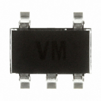
ESDA6V1SC5 STMicroelectronics, ESDA6V1SC5 Datasheet - Page 5

ESDA6V1SC5
Manufacturer Part Number
ESDA6V1SC5
Description
TRANSIL ARRAY QUAD ESD SOT23-5
Manufacturer
STMicroelectronics
Series
TRANSIL™r
Datasheet
1.ESDA5V3SC6.pdf
(11 pages)
Specifications of ESDA6V1SC5
Voltage - Reverse Standoff (typ)
5.25V
Voltage - Breakdown
6.1V
Power (watts)
400W
Polarization
4 Channel Array - Unidirectional
Mounting Type
Surface Mount
Package / Case
SOT-23-5, SC-74A, SOT-25
Polarity
Unidirectional
Operating Voltage
5.25 V
Breakdown Voltage
5.6 V
Termination Style
SMD/SMT
Peak Pulse Power Dissipation
400 W
Capacitance
190 pF
Maximum Operating Temperature
+ 125 C
Minimum Operating Temperature
- 40 C
Dimensions
1.75 mm W x 3.05 mm L x 1.45 mm H
Lead Free Status / RoHS Status
Lead free / RoHS Compliant
Other names
497-7748-2
ESDA6V1SC5
ESDA6V1SC5
Available stocks
Company
Part Number
Manufacturer
Quantity
Price
Company:
Part Number:
ESDA6V1SC5
Manufacturer:
ST
Quantity:
5 321
Company:
Part Number:
ESDA6V1SC5
Manufacturer:
ST
Quantity:
21 000
Part Number:
ESDA6V1SC5
Manufacturer:
ST
Quantity:
20 000
ESDAxxSCx
2.3
2.4
ESD protection with ESDAxxSCx
Electrostatic discharge (ESD) is a major cause of failure in electronic systems.
Transient Voltage Suppressors (TVS) are an ideal choice for ESD protection. They are
capable of clamping the incoming transient overvoltage to a low enough level such that
damage to the protected semiconductor is prevented.
Surface mount TVS arrays offer the best choice for minimal lead inductance.
They serve as parallel protection elements, connected between the signal line and ground.
As the transient rises above the operating voltage of the device, the TVS array becomes a
low impedance path diverting the transient current to ground.
Figure 10. ESDAxxSCx array protection against ESD
The ESDAxxSCx array is the ideal board level protection of ESD sensitive semiconductor
components.
The tiny SOT23-5L and SOT23-6L packages allow design flexibility in the high density
boards where the space saving is at a premium. This enables to shorten the routing and
contributes to hardening against ESD.
Advice for optimizing circuit board layout
Circuit board layout is a critical design step in the suppression of ESD induced transients.
The following guidelines are recommended:
●
●
●
●
●
The ESDAxxSC5/6 should be placed as close as possible to the input terminals or
connectors.
The path length between the ESD suppressor and the protected line should be
minimized
All conductive loops, including power and ground loops should be minimized
The ESD transient return path to ground should be kept as short as possible
Ground planes should be used whenever possible
I/ O LINES
ESDAxxxSC6
(1connection to GND for ESDAxxSC5)
sensitive
device
ESD
Application information
GND
5/11


