RZB13DHFR Sullins Connector Solutions, RZB13DHFR Datasheet - Page 65
RZB13DHFR
Manufacturer Part Number
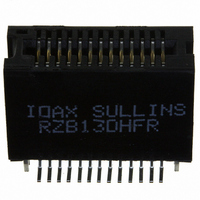
RZB13DHFR
Description
CONN EDGE DUAL .050 SMD 26 POS
Manufacturer
Sullins Connector Solutions
Datasheet
1.RZB13DHFR.pdf
(132 pages)
Specifications of RZB13DHFR
Card Type
Dual Edge
Card Thickness
0.062" (1.57mm)
Gender
Female
Number Of Positions
26
Pitch
0.050" (1.27mm)
Number Of Rows
2
Mounting Type
Surface Mount
Features
Board Lock
Contact Finish
Gold
Contact Finish Thickness
10µin (0.25µm)
Color
Black
Lead Free Status / RoHS Status
Contains lead / RoHS non-compliant
Other names
S3206


PART NUMBER CODING
DIMENSIONS
Tolerances with PPS Insulator Material may vary slightly due to shrinkage differential; Consult Factory.
POSITIONS/
CONTACTS
* Consult Factory for availability.
MATERIALS (Insulator/Contact)
CONTACT FINISH - RoHS Compliant
CONTACT CENTERS
06/12
08/16
10/20*
12/24
15/30*
18/36*
20/40*
22/44
24/48*
25/50*
28/56*
30/60*
31/62*
36/72
40/80*
43/86*
All platings are Lead Free and have .000050” Nickel underplate
G = PA9T/Phosphor Bronze
A = PPS/Beryllium Copper
M =
E = PBT/Phosphor Bronze (Standard)
R = PPS/Phosphor Bronze
C =
G =
M = .156” [3.96mm]
J = PA9T/Beryllium Copper
B =
Y =
S =
E =
(Consult Factory For Other Materials)
www.sullinscorp.com
REFER TO MOUNTING STYLE
.000100” Pure Tin, Matte
Contact Surface
Contact Surface
A±.008
.000010” Gold
.000030” Gold
.000010” Gold
.000030” Gold
.000010” Gold
.000030” Gold
0.780
1.092
1.404
1.716
2.184
2.652
2.964
3.276
3.588
3.744
4.212
4.524
4.680
5.460
6.084
6.552
Dip Solder/Wire Wrap/Right Angle for .093”[2.36] or .125”[3.18] Mating PCB
A
B
D
E
Dimensions in [ ] are in millimeters, all others are in inches.
B±.008
1.102
1.414
1.726
2.038
2.506
2.974
3.286
3.598
3.910
4.066
4.534
4.846
5.002
5.782
6.406
6.874
|
760-744-0125
C±.015
1.221
1.533
1.845
2.157
2.625
3.093
3.405
3.717
4.029
4.185
4.653
4.965
5.121
5.901
6.525
6.993
.000100” Pure Tin, Matte
.000100” Pure Tin, Matte
.000100” Pure Tin, Matte
INCHES
Overall Plating
.000005” Gold
.000005” Gold
.000010” Gold
.000010” Gold
Termination
D±.010
.297 [7.54] INSERTION DEPTH
1.534
1.846
2.158
2.470
2.938
3.406
3.718
4.030
4.342
4.498
4.966
5.278
5.434
6.214
6.838
7.306
.060
[1.52]
.156” [3.96mm] Contact Centers, .610” Insulator Height
|
toll-free 888-774-3100
E B M 43 D RM D - S273
E±.020
1.784
2.096
2.408
2.720
3.188
3.656
3.968
4.280
4.592
4.748
5.216
5.528
5.684
6.464
7.088
7.556
.156 [3.96] TYP.
F±.015
1.104
1.416
1.728
2.040
2.508
2.976
3.288
3.600
3.912
4.068
4.536
4.848
5.004
5.784
6.408
6.876
C
F
A±0.20
106.98
114.91
118.87
138.68
154.53
166.42
19.81
27.74
35.66
43.59
55.47
67.36
75.29
83.21
91.14
95.10
|
fax 760-744-6081
[9.14]
B±0.20
.360
103.28
115.16
123.09
127.05
146.86
162.71
174.60
27.99
35.92
43.84
51.77
63.65
75.54
83.46
91.39
99.31
TA, TB, TM = .025” [.64mm] Square Right Angle
-S273 =
-S664 =
MODIFICATION CODE
MOUNTING STYLE (Opposite Page)
TERMINATION TYPE (Opposite Page)
READOUT (Opposite Page)
NUMBER OF CONTACT POSITIONS
RM = .025” [.64mm] Square Wire Wrap
D = Dual
See Chart Below
RS = .025” [.64mm] Square Dip Solder
N = No Mounting
D = Flush Mounting
T = Flush Mounting With Threaded Inserts
Z = Flush Mounting With Side Holes
C±0.38
102.34
106.30
118.19
126.11
130.07
149.89
165.74
177.62
31.01
38.94
46.86
54.79
66.68
78.56
86.49
94.41
[MILLIMETERS]
FOR .093” ± .008” [2.36 ± .20]
THICK MATING PCB
FOR .125” ± .008” [3.18 ± .20]
THICK MATING PCB
[15.49]
.610
|
info@sullinscorp.com
Sullins Edgecards
D±0.25
102.36
110.29
114.25
126.14
134.06
138.02
157.84
173.69
185.57
TERMINATION TYPE,
SEE OPPOSITE PAGE
38.96
46.89
54.81
62.74
74.63
86.51
94.44
REFER TO
(Consult Factory)
E±0.51
100.79
108.71
116.64
120.60
132.49
140.41
144.37
164.19
180.04
191.92
45.31
53.24
61.16
69.09
80.98
92.86
.470 [11.94]
F±0.38
103.33
115.21
123.14
127.10
146.91
162.76
174.65
28.04
35.97
43.89
51.82
63.70
75.59
83.52
91.44
99.37
65
Related parts for RZB13DHFR
Image
Part Number
Description
Manufacturer
Datasheet
Request
R

Part Number:
Description:
CONN HEADER HM C UNSHIELD 55POS
Manufacturer:
Sullins Connector Solutions
Datasheet:

Part Number:
Description:
CONN HEADER HM B25 SHIELD 175POS
Manufacturer:
Sullins Connector Solutions
Datasheet:

Part Number:
Description:
CONN HEADER HM B25 UNSHLD 125POS
Manufacturer:
Sullins Connector Solutions
Datasheet:

Part Number:
Description:
CONN HEADER HM B25 SHIELD 125POS
Manufacturer:
Sullins Connector Solutions
Datasheet:

Part Number:
Description:
CONN HEADER HM B19 UNSHLD 95POS
Manufacturer:
Sullins Connector Solutions
Datasheet: