RZB35DHHN Sullins Connector Solutions, RZB35DHHN Datasheet - Page 83
RZB35DHHN
Manufacturer Part Number
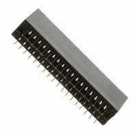
RZB35DHHN
Description
CONN EDGE DUAL .050 DIP 70 POS
Manufacturer
Sullins Connector Solutions
Datasheet
1.RZB13DHFR.pdf
(132 pages)
Specifications of RZB35DHHN
Card Type
Dual Edge
Card Thickness
0.062" (1.57mm)
Gender
Female
Number Of Positions
70
Pitch
0.050" (1.27mm)
Number Of Rows
2
Mounting Type
Through Hole
Contact Finish
Gold
Contact Finish Thickness
10µin (0.25µm)
Color
Black
Lead Free Status / RoHS Status
Contains lead / RoHS non-compliant
Features
-
Other names
S3127


PLATING - RoHS Compliant
INSULATOR MATERIAL
CONTACT CENTERS
NUMBER OF POSITIONS
READOUT
TERMINATION TYPE
See applicable specifi cation pages for more information.
Specifications are subject to change without notice.
* Requires ‘K’ Modifi cation Code
Platings that start with ‘E’ are for Economy Eyelet Only
Other Plating and thicknesses available upon request.
*EMPSL =
*MPSL =
*EMPL = .000100” Overall Pure Tin, Matte
EMPP = Spinodal Contact Material
02 - 70 Contacts Per Row
ALL PLATINGS ARE LEAD FREE AND HAVE
*MPL = .000100” Overall Pure Tin, Matte
All Materials are U.L. Approved 94V-0
100 = .100” [2.54mm]
125 = .125” [3.18mm]
150 = .150” [3.84mm]
156 = .156” [3.96mm]
MPP = Spinodal Contact Material
EMP = .000010” Overall Gold
WE = .025” Square Card Extender -
FS = .045” Square Tails - .720” Insulator Height
PE = Economy Eyelet - .431” Insulator Height,
SE = Card Extender - .431” Insulator Height
MP = .000010” Overall Gold
W = .025” Square Wire Wrap -
D = Dual Row
P = Solder Eyelet - .431” Insulator Height
R = .026” Round Tails - .610” Insulator Height,
S = Dip Solder - .431” Insulator Height
0 = PBT, Blue
1 = PPS, Brown
2 = PBT, Green
3 = PBT, Black
4 = PA9T, Black
5 = PPS, Black
6 = PPS, Green
7 = PPS, Brown
8 = Peek, Natural
www.sullinscorp.com
.000050” NICKEL UNDERPLATE
Contact Surface
(Overall Gold Only)
(Overall Gold Only)
Card Extender, .156” only
.610” Insulator Height
.610” Insulator Height
.000010” Gold .000100” Pure Tin Matte
.000010” Gold .000100” Pure Tin Matte
|
_ MP_ _ - 0 100 - 22 - D W - 5 xxx
Termination
760-744-0125
|
toll-free 888-774-3100
10 = One Ear, #4-40 Threaded Insert
11 = .142” Mounting Holes
12 = .128” Clearance Holes
13 = Flush Ears, .128” Clearance Holes
14 = .142” Side Holes (Cross Drilled)
15 = Flush Ears, .125” Clearance Holes
16 = Flush .250” Ears to top of the
18 = Flush Ears, .125” Side Holes
19 = .152” Clearance Holes
58 = Raised Ears, .125” Side Holes
81 = Flush Ears, .125” Side Holes
86 = Side Holes with #4-40 Threaded Insert
1 = .125” Clearance Holes
2 = #4-40 Threaded Insert
3 = Floating Bobbin
4 = No Mounting Ears
5 = Raised with .125” Clearance Holes
6 = Raised with #4-40 Threaded Insert
8 = .125” Side Holes (Cross Drilled)
9 = One Ear, .125” Clearance Hole
.245” Ears, .431” Insulator Height
.250” Flush Ears, .610” Insulator Height
.245” Ears, .431” Insulator Height
.250” Flush Ears, .610” Insulator Height
.220” Ears not Including Bobbin
on All Connectors
(Flush Ears on .610 Insulator Height )
Wire Wrap Only, .610” Insulator Height
Wire Wrap Only, .610” Insulator Height
Dip Solder & Eyelet
Dip Solder & Eyelet
.431” Insulator Height, Dip Solder, Eyelet
.610” Insulator Height, Wire Wrap
.431” Insulator Height, Dip Solder & Eyelet
.610” Insulator Height, Wire Wrap
.430” Ears with Pad on .610” Insulator
Height, Wire Wrap Only
.431” Insulator Height, Dip Solder, Eyelet
.610” Insulator Height, Wire Wrap
.190” Ears, No Pad
.610” Insulator Height, Wire Wrap Only
Card Entry Side of the Connector,
.610” Insulator Height, Wire Wrap Only
(Cross Drilled)
.610” Insulator Height, Wire Wrap Only
(Cross Drilled)
.250” Ears with Pad, .610” Insulator Height,
Wire Wrap
.250” Ears with Pad, .610” Insulator Height
All Connectors
MOUNTING STYLE
|
fax 760-744-6081
PART NUMBER OPTIONS
Micro Plastics Edgecards
|
info@sullinscorp.com
CONSULT FACTORY FOR OTHER OPTIONS
X9 = .200” Row Spacing for
E9 = .200” Row Spacing on .156”
F9 = 6.802” Cardslot and .200” Row
TT = No Standoffs
M = Pad on Bottom of Mounting Ears
D = .000050” Gold Plating -
Q = Right Angle Connector Contacts
A = Contacts Loaded one side only
G = .000030” Gold Plating
H = .190” Contact Length for .025”
N = Hi-light Contact ID on Bottom
U = .000020” Gold Plating
B = Center Barrier for 28/56 -
C = .030” Longer Cardslot and
K = MPSL - Selective Gold with Pure
P = Engraving Reversed
R = Right Angle Connectors
Y = Beryllium Copper Contacts
Z = Standoffs on .156” Wire Wrap
F = 6.802” Cardslot for 43/86
L = .140” Contact Length for
S = Shorter Overall Length
T = Center Standoffs Removed
J = Low Insertion Force
MODIFICATION CODE
.156” Dip Solder & Eyelet
Mounting Hole Centers for 22/44,
All .156” (Consult Factory)
(Consult Factory)
Contact Centers
.156” Eyelet & Wire Wrap Only
Spacing for 43/86 Dip Solder Only
Square & .026” Round Contacts
.250” Contact Length without
Standoffs
Tin, Matte Plating on Tails
MPL - Overall Pure Tin, Matte
.156” Dip Solder Only
for .156” , .431” Insulator Height,
Dip Solder & Eyelet Only
(Consult Factory)
(Consult Factory)
Untrimmed
(Requires ‘R’ Modifi cation Code)
.100” & .125” Wire Wrap Only
.100” & .156” Dip Solder Only
.250” Row Spacing for
.125” Dip Solder Only
83
Related parts for RZB35DHHN
Image
Part Number
Description
Manufacturer
Datasheet
Request
R

Part Number:
Description:
CONN HEADER HM C UNSHIELD 55POS
Manufacturer:
Sullins Connector Solutions
Datasheet:

Part Number:
Description:
CONN HEADER HM B25 SHIELD 175POS
Manufacturer:
Sullins Connector Solutions
Datasheet:

Part Number:
Description:
CONN HEADER HM B25 UNSHLD 125POS
Manufacturer:
Sullins Connector Solutions
Datasheet:

Part Number:
Description:
CONN HEADER HM B25 SHIELD 125POS
Manufacturer:
Sullins Connector Solutions
Datasheet:

Part Number:
Description:
CONN HEADER HM B19 UNSHLD 95POS
Manufacturer:
Sullins Connector Solutions
Datasheet: