RZB60DHFR Sullins Connector Solutions, RZB60DHFR Datasheet - Page 123
RZB60DHFR
Manufacturer Part Number
RZB60DHFR
Description
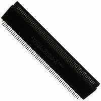
CONN EDGE DUAL .050 SMD 120 POS
Manufacturer
Sullins Connector Solutions
Datasheet
1.RZB13DHFR.pdf
(132 pages)
Specifications of RZB60DHFR
Card Type
Dual Edge
Card Thickness
0.062" (1.57mm)
Gender
Female
Number Of Positions
120
Pitch
0.050" (1.27mm)
Number Of Rows
2
Mounting Type
Surface Mount
Features
Board Lock
Contact Finish
Gold
Contact Finish Thickness
10µin (0.25µm)
Color
Black
Lead Free Status / RoHS Status
Contains lead / RoHS non-compliant
Other names
S3217


PART NUMBER CODING
DIMENSIONS
** SEE PAGES 82-83 FOR SPECIFICATIONS AND OTHER VARIATIONS
PLATING - RoHS Compliant
* Consult Factory for availability.
I
CONTACT CENTERS
NUMBER OF POSITIONS
READOUT
POSITIONS/
All Platings are Lead Free and have .000050” Nickel Underplate
*Requires ‘K’ Modifi cation Code
CONTACTS
[9.40]
*MPSL =
NSULATOR MATERIAL**
.370
*MPL =
06/12
08/16
10/20
12/24
15/30
18/36
20/40*
22/44
24/48
25/50
28/56
30/60
31/62
36/72
40/80
43/86
Contacts Per Row (See Position Chart Below)
156 = .156” [3.96mm]
MP =
D = Dual
0 = PBT
www.sullinscorp.com
.000010” Gold
.000100” Overall Pure Tin, Matte
.000010” Overall Gold
Contact Surface
A±.008
0.780
1.092
1.404
1.716
2.184
2.652
2.964
3.276
3.588
3.744
4.212
4.524
4.680
5.460
6.084
6.552
REFER TO MOUNTING STYLE
Dimensions in [ ] are in millimeters, all others are in inches.
D
B
A
E
B±.008
1.102
1.414
1.726
2.038
2.506
2.974
3.286
3.598
3.910
4.066
4.534
4.846
5.002
5.782
6.406
6.874
|
760-744-0125
.000100” Pure Tin, Matte
C±.015
1.221
1.533
1.845
2.157
2.625
3.093
3.405
3.717
4.029
4.185
4.653
4.965
5.121
5.901
6.525
6.993
Termination
INCHES
[6.35]
.250
D±.010
1.534
1.846
2.158
2.470
2.938
3.406
3.718
4.030
4.342
4.498
4.966
5.278
5.434
6.214
6.838
7.306
.060[1.52]
MPSL - 0 156 - 10 - D W - 1 K R
|
toll-free 888-774-3100
.297 [7.54] INSERTION DEPTH
E±.020
1.784
2.096
2.408
2.720
3.188
3.656
3.968
4.280
4.592
4.748
5.216
5.528
5.684
6.464
7.088
7.556
.025[.64]
.156” Contact Centers, .610” Insulator Height,
F±.015
C
1.030
1.342
1.654
1.966
2.434
2.902
3.214
3.526
3.838
3.994
4.462
4.774
4.930
5.710
6.334
6.802
F
106.98
114.91
118.87
138.68
154.53
166.42
A±0.20
19.81
27.74
35.66
43.59
55.47
67.36
75.29
83.21
91.14
95.10
.156[3.96]
|
fax 760-744-6081
103.28
115.16
123.09
127.05
146.86
162.71
174.60
B±0.20
[15.49]
27.99
35.92
43.84
51.77
63.65
75.54
83.46
91.39
99.31
.610
.180[4.57]
MOUNTING STYLE
TERMINATION TYPE
Omit for MP Plating (Overall Gold)
W = .025 [.64] Square
MODIFICATION CODE**
R = Right Angle
PLATING MODIFICATION CODE**
Micro Plastics Edgecards
K = Required on MPSL or MPL Plating
1 = .125” Clearance Hole
2 = #4-40 Threaded Insert
4 = No Mounting
5 = Raised, .125” Clearance Hole
6 = Raised, #4-40 Threaded Insert
8 = Raised, Side Mounting,
LOOP BELLOWS
102.34
106.30
118.19
126.11
130.07
149.89
165.74
177.62
C±0.38
31.01
38.94
46.86
54.79
66.68
78.56
86.49
94.41
[MILLIMETERS]
.125” Clearance Hole
|
info@sullinscorp.com
A
1
102.36
110.29
114.25
126.14
134.06
138.02
157.84
173.69
185.57
D±0.25
38.96
46.89
54.81
62.74
74.63
86.51
94.44
B
2
CONTACT MARKINGS
(LETTERS G, I, O & Q NOT USED)
SIZES 06-25 & 30
1 2 . . . 23 24 . . . 29 30
A B . . . A B . . . H J
SIZES 28 & 31
1 2 . . . 23 24 . . . 30 31
A B . . . A B . . . J
SIZES 36 - 43
A B . . . A B . . . X Y
1 2 . . . 23 24 . . . 42 43
3
C
141 142 143
(See Opposite Page)
W
Right Angle
X
100.79
108.71
116.64
120.60
132.49
140.41
144.37
164.19
180.04
191.92
E±0.51
45.31
53.24
61.16
69.09
80.98
92.86
Y
101.45
113.33
121.26
125.22
145.03
160.88
172.77
K
F±0.38
26.16
34.09
42.01
49.94
61.82
73.71
81.64
89.56
97.49
123
Related parts for RZB60DHFR
Image
Part Number
Description
Manufacturer
Datasheet
Request
R

Part Number:
Description:
CONN HEADER HM C UNSHIELD 55POS
Manufacturer:
Sullins Connector Solutions
Datasheet:

Part Number:
Description:
CONN HEADER HM B25 SHIELD 175POS
Manufacturer:
Sullins Connector Solutions
Datasheet:

Part Number:
Description:
CONN HEADER HM B25 UNSHLD 125POS
Manufacturer:
Sullins Connector Solutions
Datasheet:

Part Number:
Description:
CONN HEADER HM B25 SHIELD 125POS
Manufacturer:
Sullins Connector Solutions
Datasheet:

Part Number:
Description:
CONN HEADER HM B19 UNSHLD 95POS
Manufacturer:
Sullins Connector Solutions
Datasheet: