3120-F311-P7T1-W01D-15A E-T-A, 3120-F311-P7T1-W01D-15A Datasheet - Page 13
3120-F311-P7T1-W01D-15A
Manufacturer Part Number
3120-F311-P7T1-W01D-15A
Description
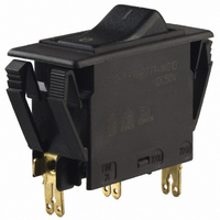
CIRCUIT BREAKER ROCKER SP 15A BK
Manufacturer
E-T-A
Series
3120-Fr
Datasheet
1.3120-F311-P7T1-W01D-20A.pdf
(16 pages)
Specifications of 3120-F311-P7T1-W01D-15A
Breaker Type
Thermal
Voltage
50VDC, 250VAC
Current - Trip (it)
15A
Number Of Poles
1
Actuator Type
Rocker
Mounting Type
Panel Mount
Lead Free Status / RoHS Status
Lead free / RoHS Compliant
Other names
302-1180
3120-F311-P7T1-W01D-15AMP
3120-F311-P7T1-W01D-15AMP


A module supplied factory fitted to type 3120-F to provide electrically
separate changeover contacts which operate as the main contacts open/
close. Ideally suited to status signalling and sequence switching.
Monitoring of the switching position of the circuit breaker or any connected
load.
Type No.
X3120
X3120 - S 0
Authority
VDE (EN 60934)
UL, CSA
Issue B
Description
Typical applications
Ordering information
Approvals (complete circuit breaker/module assembly)
(230209)
Module for type 3120 and type 3140
Function
S
auxiliary contact module
Contact configuration
0
change-over contact
Terminal design
1
1
blade terminals 2.8 x 0.5 (QC .110), silver plated
Contact rating
A
B
A M
AC
Voltage rating Current rating
10 V-250 V
5 V-250 V
Supply condition
M
Auxiliary Contact Module X3120-S for circuit breaker 3120-F...
Voltage ratings
AC 250 V; DC 28 V
AC 250 V
module mounted to circuit breaker 3120-...
ordering example
0.1...4 A
0.05...1 A
DC (not approved)
Voltage rating Current rating
12 V
24 V
60 V
110 V
220 V
5 V-250 V
Current ratings
0.05...4 A
0.05...4 A
0.1...4 A
0.1...4 A
0.1...1 A
0.1...0,5 A
0.1...0.25 A
0.05...1 A
www.e-t-a.com
Shock
Corrosion
Humidity
Voltage rating
Current rating
Typical life
Ambient temperature
Dielectric strength
(IEC 60664 and 60664A)
Insulation resistance
Vibration
Mass
This is a metric design and millimeter dimensions take precedence ( mm )
All dimensions without tolerances are for reference only. In the interest of improved design,
performance and cost effectiveness the right to make changes in these specifications
without notice is reserved.Product markings may not be exactly as the ordering codes.
Errors and omissions excepted.
Dimensions
Internal connection diagram
Technical data
between main and
auxiliary circuit
.827
21
12(i)
12(k)
blade terminalsDIN 46244-A2.8-0.5-Ms (QC .110)
silver plated
11
line
load
AC 250 V; DC 220 V
0.1...4 A / 0.05...1 A
50,000 operations
-30...+60 °C (-22...+140 °F)
test voltage
AC 3,000 V
> 100 MΩ (DC 500 V)
6 g (type X3120-S...A)
8 g (type X3120-S...B)
(57-500 Hz), ± 0.46 mm (10-57 Hz)
to IEC 60068-2-6, test Fc
10 frequency cycles/axis
15 g (11 ms), type X3120-S...A
20 g (11 ms), type X3120-S...B
to IEC 60068-2-27, test Ea
96 hours at 5 % salt mist,
to IEC 60068-2-11, test Ka
240 hours at 95 % RH
to IEC 60068-2-78, test Cab
approx. 38 g (complete assembly)
21
22(i)
22(k)
34
.295 .295
.394
7.5 7.5
10
19.8
.780
31
32
module mounted
.551
.079
14
2
inch
1 - 71
1
Related parts for 3120-F311-P7T1-W01D-15A
Image
Part Number
Description
Manufacturer
Datasheet
Request
R

Part Number:
Description:
CIRCUIT BREAKR THERMAL 2POLE 12A
Manufacturer:
E-T-A
Datasheet:

Part Number:
Description:
CIRCUIT BREAKER ROCKER SP 12A
Manufacturer:
E-T-A
Datasheet:

Part Number:
Description:
CIRCUIT BREAKER ROCKER SP 5A
Manufacturer:
E-T-A
Datasheet:
Part Number:
Description:
CIRCUIT BREAKER ROCKER 2.5 AMP
Manufacturer:
E-T-A
Datasheet:
Part Number:
Description:
CIRCUIT BREAKER ROCKER SP 20A BK
Manufacturer:
E-T-A
Datasheet:
Part Number:
Description:
CIRCUIT BREAKER ROCKER SP 10A BK
Manufacturer:
E-T-A
Datasheet:
Part Number:
Description:
CIRCUIT BREAKER ROCKER SP 5A BK
Manufacturer:
E-T-A
Datasheet:
Part Number:
Description:
CIRCUIT BREAKER ROCKER SP 1A BK
Manufacturer:
E-T-A
Datasheet:
Part Number:
Description:
CIRCUIT BREAKER ROCKR SP 10A WHT
Manufacturer:
E-T-A
Datasheet:
Part Number:
Description:
CIRCUIT BREAKER ROCKER SP 5A WHT
Manufacturer:
E-T-A
Datasheet:
Part Number:
Description:
CIRCUIT BREAKER ROCKER SP 2A BK
Manufacturer:
E-T-A
Datasheet:
Part Number:
Description:
CIRCUIT BREAKER ROCKER SP 2A WHT
Manufacturer:
E-T-A
Datasheet:

Part Number:
Description:
CIRCUIT BREAKER VERT PCB 8A
Manufacturer:
E-T-A
Datasheet:
Part Number:
Description:
CIRCUIT BREAKER VERT PCB 5A
Manufacturer:
E-T-A
Datasheet:
Part Number:
Description:
Circuit Breaker, Single Pole, 250VAC 48 VDC, 0.05A
Manufacturer:
E-T-A Circuit Protection & Control