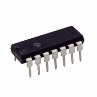
PIC16F505-I/P Microchip Technology, PIC16F505-I/P Datasheet - Page 7

PIC16F505-I/P
Manufacturer Part Number
PIC16F505-I/P
Description
IC MCU FLASH 1KX12 14DIP
Manufacturer
Microchip Technology
Series
PIC® 16Fr
Datasheets
1.PIC12F509T-ISN.pdf
(110 pages)
2.PIC16F505-IST.pdf
(4 pages)
3.PIC16F505-IST.pdf
(22 pages)
4.PIC12F509-EMC.pdf
(106 pages)
Specifications of PIC16F505-I/P
Program Memory Type
FLASH
Program Memory Size
1.5KB (1K x 12)
Package / Case
14-DIP (0.300", 7.62mm)
Core Processor
PIC
Core Size
8-Bit
Speed
20MHz
Peripherals
POR, WDT
Number Of I /o
11
Ram Size
72 x 8
Voltage - Supply (vcc/vdd)
2 V ~ 5.5 V
Oscillator Type
Internal
Operating Temperature
-40°C ~ 85°C
Processor Series
PIC16F
Core
PIC
Data Bus Width
8 bit
Data Ram Size
72 B
Interface Type
RS- 232, USB
Maximum Clock Frequency
20 MHz
Number Of Programmable I/os
12
Number Of Timers
1
Operating Supply Voltage
2 V to 5.5 V
Maximum Operating Temperature
+ 85 C
Mounting Style
Through Hole
3rd Party Development Tools
52715-96, 52716-328, 52717-734
Development Tools By Supplier
PG164130, DV164035, DV244005, DV164005, PG164120, ICE2000
Minimum Operating Temperature
- 40 C
Lead Free Status / RoHS Status
Lead free / RoHS Compliant
For Use With
AC162070 - HEADER INTRFC MPLAB ICD2 8/14PAC162059 - HEADER INTRFC MPLAB ICD2 8/14PINDM163029 - BOARD PICDEM FOR MECHATRONICSDVA16XP140 - ADAPTER DEVICE FOR MPLAB-ICEAC124001 - MODULE SKT PROMATEII 8DIP/SOIC
Eeprom Size
-
Data Converters
-
Connectivity
-
Lead Free Status / Rohs Status
Lead free / RoHS Compliant
3.1.2.5
The End Programming command terminates the
program process. A delay of T
required before the next command to allow the internal
programming voltage to discharge (see Figure 3-6).
FIGURE 3-6:
3.1.2.6
After this command is performed, the entire program
memory and Configuration Word is erased.
To perform a Bulk Erase of the program memory and
configuration fuses, the following sequence must be
performed (see Figure 3-12).
1.
2.
3.
4.
5.
2010 Microchip Technology Inc.
Note 1: A fully erased part will read ‘1’s in every
Read and save 0x3FF oscillator Calibration bits
and 0x404 backup OSCCAL bits into computer/
programmer temporary memory.
Enter Program/Verify mode. PC is set to
Configuration Word address.
Perform a Bulk Erase Program Memory
command.
Wait T
Restore OSCCAL bits.
2: The oscillator Calibration bits are erased
ICSPCLK
ICSPDAT
ERA
program memory location.
if a Bulk Erase is invoked. They must be
read and saved prior to erasing the
device and restored during the program-
ming operation. Oscillator Calibration bits
are stored at the Reset vector as the
operand of a MOVLW instruction.
End Programming
Bulk Erase Program Memory
to complete Bulk Erase.
END PROGRAMMING (EXTERNALLY TIMED)
DIS
1
0
(see Table 6-1) is
2
1
Preliminary
T
3
1
SET
1
4
1
To perform a full device Bulk Erase of the program
memory, configuration fuses, user IDs and backup
OSCCAL, the following sequence must be performed
(see Figure 3-13).
1.
2.
3.
4.
5.
6.
7.
T
HLD
Read and save 0x3FF oscillator Calibration bits
and 0x404 backup OSCCAL bits into computer/
programmer temporary memory.
Enter Program/Verify mode.
Increment PC to 0x400 (first user ID location).
Perform a Bulk Erase command.
Wait T
Restore OSCCAL bits.
Restore backup OSCCAL bits.
5
x
1
ERA
6
x
to complete Bulk Erase.
T
DIS
1
Next Command
PIC16F505
2
DS41226G-page 7


