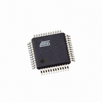
ATMEGA406-1AAU Atmel, ATMEGA406-1AAU Datasheet - Page 25

ATMEGA406-1AAU
Manufacturer Part Number
ATMEGA406-1AAU
Description
IC AVR MCU 40K 1MHZ 48LQFP
Manufacturer
Atmel
Series
AVR® ATmegar
Specifications of ATMEGA406-1AAU
Core Processor
AVR
Core Size
8-Bit
Speed
1MHz
Connectivity
I²C
Peripherals
POR, WDT
Number Of I /o
18
Program Memory Size
40KB (20K x 16)
Program Memory Type
FLASH
Eeprom Size
512 x 8
Ram Size
2K x 8
Voltage - Supply (vcc/vdd)
4 V ~ 25 V
Data Converters
A/D 10x12b
Oscillator Type
Internal
Operating Temperature
-30°C ~ 85°C
Package / Case
48-LQFP
Processor Series
ATMEGA48x
Core
AVR8
Data Bus Width
8 bit
Data Ram Size
2 KB
Interface Type
2-Wire
Maximum Clock Frequency
1 MHz
Number Of Programmable I/os
18
Number Of Timers
2
Maximum Operating Temperature
+ 85 C
Mounting Style
SMD/SMT
3rd Party Development Tools
EWAVR, EWAVR-BL
Development Tools By Supplier
ATAVRDRAGON, ATSTK500, ATSTK600, ATAVRISP2, ATAVRONEKIT
Minimum Operating Temperature
- 30 C
Cpu Family
ATmega
Device Core
AVR
Device Core Size
8b
Frequency (max)
1MHz
Total Internal Ram Size
2KB
# I/os (max)
18
Number Of Timers - General Purpose
2
Operating Supply Voltage (typ)
5/9/12/15/18/24V
Operating Supply Voltage (max)
25V
Operating Supply Voltage (min)
4V
On-chip Adc
10-chx12-bit
Instruction Set Architecture
RISC
Operating Temp Range
-30C to 85C
Operating Temperature Classification
Commercial
Mounting
Surface Mount
Pin Count
48
Package Type
LQFP
Controller Family/series
AVR MEGA
No. Of I/o's
18
Eeprom Memory Size
512Byte
Ram Memory Size
2KB
Cpu Speed
1MHz
Rohs Compliant
Yes
For Use With
770-1007 - ISP 4PORT ATMEL AVR MCU SPI/JTAG770-1005 - ISP 4PORT FOR ATMEL AVR MCU JTAG770-1004 - ISP 4PORT FOR ATMEL AVR MCU SPI
Lead Free Status / RoHS Status
Lead free / RoHS Compliant
Available stocks
Company
Part Number
Manufacturer
Quantity
Price
Part Number:
ATMEGA406-1AAU
Manufacturer:
AT
Quantity:
20 000
2548ES–AVR–07/06
4. Voltage Regulator Start-up sequence
5.
6. EEPROM read from application code does not work in Lock Bit Mode 3
When powering up ATmega406 some precautions are necessary to ensure proper start-up
of the Voltage Regulator.
Problem Fix/Workaround
The three steps below are needed to ensure proper start-up of the voltage regulator.
a. Do NOT connect a capacitor larger than 100 nF on the VFET pin. This is to ensure
b. During assembly, always connect Cell1 first, then Cell2 and so on until the top cell is
c. After all cells have been assembled as described in step 2, a charger source must be
If the Voltage Regulator started up in Power-off during assembly of the cells, the chip will ini-
tialize when the charger source makes the voltage at the BATT pin exceed 7 - 8 Volts.
If the Voltage Regulator did not start up properly, the charger source has one additional
requirement to ensure proper start up and initialization. In this case the charger source must
ensure that the voltage at the VFET pin increases quickly at least 3 Volts above the voltage
at the PVT pin, and that the voltage at the BATT pin exceeds 7 - 8 Volts. This will start up
and initialize the chip directly.
The reference voltage at the V
a. Charger Over-current and/or Discharge Over-current Protection active but Short-cir-
b. Short-circuit Protection active. Short-circuit measurements are activated when SCD
c. V-ADC conversion of the internal VTEMP voltage. This will increase V
Problem Fix/Work around
To ensure the highest accuracy, set the Bandgap Calibration Register (BGCC) to get 1.100
V at V
charge FET is enabled.
When the Memory Lock Bits LB2 and LB1 are programmed to mode 3, EEPROM read does
not work from the application code.
Problem Fix/Work around
Do not set Lock Bit Protection Mode 3 when the application code needs to read from
EEPROM.
V
REF
fast rise time on the VFET pin when a supply voltage is connected.
connected to PVT. If the cell voltages are about 2 volts or larger, the Voltage Regula-
tor will normally start up properly in Power-off mode (VREG appr. 2.8 volts).
connected at the BATT+ terminal to initialize the chip, see
Reset and Charger Connect” on page 38
cuit inactive. This will increase V
condition were all Current Protections are disabled.
in BPCR is zero (default) and DFE in FET Control and Status Register (FCSR) is set.
This will increase V
circuit measurements inactive.
with typical 15 mV compared to a condition with short-circuit measurements inactive.
influenced by MCU state
REF
after the chip is configured with the actual Battery Protection settings and the Dis-
REF
voltage with typical 8 mV compared to a condition with short-
REF
pin depends on the following conditions of the device:
REF
voltage with typical 1 mV compared to a
in the datasheet.
Section 8.3 ”Power-on
ATmega406
REF
voltage
25


