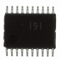
R5F21191SP#U0 Renesas Electronics America, R5F21191SP#U0 Datasheet - Page 269

R5F21191SP#U0
Manufacturer Part Number
R5F21191SP#U0
Description
IC R8C MCU FLASH 8K 20SSOP
Manufacturer
Renesas Electronics America
Series
M16C™ M16C/R8C/Tiny/19r
Datasheets
1.R5F211A2SPU0.pdf
(300 pages)
2.R5F21181DSPU0.pdf
(43 pages)
3.R5F21181DSPU0.pdf
(259 pages)
Specifications of R5F21191SP#U0
Core Processor
R8C
Core Size
16-Bit
Speed
20MHz
Connectivity
SIO, UART/USART
Peripherals
LED, POR, Voltage Detect, WDT
Number Of I /o
13
Program Memory Size
4KB (4K x 8)
Program Memory Type
FLASH
Ram Size
384 x 8
Voltage - Supply (vcc/vdd)
2.7 V ~ 5.5 V
Data Converters
A/D 4x1b
Oscillator Type
Internal
Operating Temperature
-20°C ~ 85°C
Package / Case
20-SSOP
For Use With
R0K521134S000BE - KIT EVAL STARTER FOR R8C/13R0E521174CPE10 - EMULATOR COMPACT R8C/18/19/1
Lead Free Status / RoHS Status
Lead free / RoHS Compliant
Eeprom Size
-
- Current page: 269 of 300
- Download datasheet (2Mb)
Rev.2.00 Oct 17, 2005
REJ09B0001-0200
5.2 Interrupt Control
Chapter 5
This section explains how to enable/disable maskable interrupts and set acknowledge priority. The expla-
nation here does not apply to non-maskable interrupts.
Maskable interrupts are enabled and disabled by using the I flag, IPL, and bits ILVL2 to ILVL0 in each
interrupt control register. Whether or not an interrupt is requested is indicated by the IR bit in each interrupt
control register.
For details about the memory allocation and the configuration of interrupt control registers, refer to the
R8C’s hardware manual.
Figure 5.2.1 Timing with Which Changes of I Flag are Reflected in Interrupt Handling
5.2.1 I Flag
5.2.2 IR Bit
When changed by REIT instruction
When changed by FCLR, FSET, POPC, or LDC instruction
The I flag is used to disable/enable maskable interrupts. When the I flag is set to 1 (enabled), all
maskable interrupts are enabled; when the I flag is cleared to 0 (disabled), they are disabled.
When the I flag is changed, the altered flag status is reflected in determining whether or not to accept an
interrupt request with the following timing:
The IR bit is set to 1 (interrupt requested) when an interrupt request is generated. The IR bit is cleared to
0 (interrupt not requested) after the interrupt request is acknowledged and the program branches to the
corresponding interrupt vector.
The IR bit can be cleared to 0 by a program. Do not set it to 1.
• If the flag is changed by an REIT instruction, the changed status takes effect beginning with the
• If the flag is changed by an FCLR, FSET, POPC, or LDC instruction, the changed status takes
REIT instruction.
effect beginning with the next instruction.
Interrupt request generated
Interrupts
Interrupt request generated
page 249 of 263
Previous
instruction
(If I flag is changed from 0 to 1 by REIT instruction)
Previous
instruction
(If I flag is changed from 0 to 1 by FSET instruction)
Determination whether or not to
accept interrupt request
FSET I
REIT
Interrupt sequence
Next instruction
Determination whether or not to
accept interrupt request
Interrupt sequence
Ti m e
Ti m e
5.2 Interrupt Control
Related parts for R5F21191SP#U0
Image
Part Number
Description
Manufacturer
Datasheet
Request
R

Part Number:
Description:
KIT STARTER FOR M16C/29
Manufacturer:
Renesas Electronics America
Datasheet:

Part Number:
Description:
KIT STARTER FOR R8C/2D
Manufacturer:
Renesas Electronics America
Datasheet:

Part Number:
Description:
R0K33062P STARTER KIT
Manufacturer:
Renesas Electronics America
Datasheet:

Part Number:
Description:
KIT STARTER FOR R8C/23 E8A
Manufacturer:
Renesas Electronics America
Datasheet:

Part Number:
Description:
KIT STARTER FOR R8C/25
Manufacturer:
Renesas Electronics America
Datasheet:

Part Number:
Description:
KIT STARTER H8S2456 SHARPE DSPLY
Manufacturer:
Renesas Electronics America
Datasheet:

Part Number:
Description:
KIT STARTER FOR R8C38C
Manufacturer:
Renesas Electronics America
Datasheet:

Part Number:
Description:
KIT STARTER FOR R8C35C
Manufacturer:
Renesas Electronics America
Datasheet:

Part Number:
Description:
KIT STARTER FOR R8CL3AC+LCD APPS
Manufacturer:
Renesas Electronics America
Datasheet:

Part Number:
Description:
KIT STARTER FOR RX610
Manufacturer:
Renesas Electronics America
Datasheet:

Part Number:
Description:
KIT STARTER FOR R32C/118
Manufacturer:
Renesas Electronics America
Datasheet:

Part Number:
Description:
KIT DEV RSK-R8C/26-29
Manufacturer:
Renesas Electronics America
Datasheet:

Part Number:
Description:
KIT STARTER FOR SH7124
Manufacturer:
Renesas Electronics America
Datasheet:

Part Number:
Description:
KIT STARTER FOR H8SX/1622
Manufacturer:
Renesas Electronics America
Datasheet:

Part Number:
Description:
KIT DEV FOR SH7203
Manufacturer:
Renesas Electronics America
Datasheet:


