DS2250-32-16+ Maxim Integrated Products, DS2250-32-16+ Datasheet
DS2250-32-16+
Specifications of DS2250-32-16+


Related parts for DS2250-32-16+


DS2250-32-16+ Summary of contents
Page 1
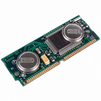
... PIN CONFIGURATION DS2250( 40-Pin SIMM ORDERING INFORMATION PART RAM SIZE (kB) DS2250-32-16 DS2250-32-16+ DS2250-64-16 DS2250-64-16# DS2250T-32-16 DS2250T-32-16+ DS2250T-64-16 DS2250T-64-16+ + Denotes lead-free/RoHS-compliant package # Denotes RoHS-compliant device that may contain lead exempt under the RoHS requirements. Soft Microcontroller Module FEATURES . The ...
Page 2
... DS2250(T) BLOCK DIAGRAM Figure ...
Page 3
... PSEN DS2250(T) is already in a reset state. The device that pulls down should be open-drain since it must not interfere with ALE - Address Latch Enable. Used to de-multiplex the multiplexed Expanded Address/Data bus on Port 0. This pin is normally connected to the clock input ’ ...
Page 4
... A second 32k RAM is available for data only. The Real Time Clock (RTC) in the DS2250(T) is reached in the memory map by setting a SFR bit. The MCON.2 bit (ECE2) is used to select an alternate data memory map. While ECE2=1, all MOVXs will be routed to this alternate memory map. The real time clock is a serial device that resides in this area. A full description of the RTC access and example software is given in the Secure Microcontroller User’ ...
Page 5
... Parallel Program Load cycles which perform the initial loading from parallel address/data information presented on the I/O port pins. This mode is timing set-compatible with the 87C51H microcontroller programming mode. The DS2250(T) is placed in its Program Load configuration by simultaneously applying a logic 1 to the RST pin and forcing the PSEN will look for a parallel Program Load pulse serial ASCII carriage return (0DH) character received at 9600, 2400, 1200, or 300 bps over the serial port ...
Page 6
... DS2250(T) nonvolatile RAM. Communication can be performed over a standard asynchronous serial communications port. A typical application would use a simple RS232C serial interface to program the DS2250( final production procedure. The hardware configuration which is required for the Serial Program Load Mode is illustrated in Figure 3. Port pins 2.7 and 2 ...
Page 7
... The DS89C450-K00 evaluation kit can be used to develop and test user code. It allows the user to download Intel hex formatted code to the DS2250(T) from a PC. The user must purchase the DS2250 and DS9072-40V mechanical adapter separately. Refer to the Secure Microcontroller User’s Guide for further details ...
Page 8
... IN CC RST, Pulldown Resistor EA Stop Mode Current Power Fail Warning Voltage Minimum Operating Voltage Programming Supply Voltage (Parallel Program Mode) Program Supply Current Operating Current DS2250-8k DS2250-32k @ 12 MHz DS2250(T)-64- MHz Idle Mode Current @ 8 MHz SYMBOL MIN V -0 2.0 IH1 V 3.5 IH2 ...
Page 9
AC CHARACTERISTICS—EXPANDED BUS MODE TIMING SPECIFICATIONS = 5V ±5 0°C to +70°C PARAMETER 1 Oscillator Frequency 2 ALE Pulse Width 3 Address Valid to ALE Low 4 Address Hold After ALE Low 5 ALE ...
Page 10
EXPANDED PROGRAM MEMORY READ CYCLE EXPANDED DATA MEMORY READ CYCLE ...
Page 11
EXPANDED DATA MEMORY WRITE CYCLE EXTERNAL CLOCK TIMING ...
Page 12
AC CHARACTERISTICS—EXTERNAL CLOCK DRIVE = 5V ±5 0°C to +70°C PARAMETER 28 External Clock High Time 29 External Clock Low Time 30 External Clock Rise Time 31 External Clock Fall Time AC CHARACTERISTICS—SERIAL PORT ...
Page 13
AC CHARACTERISTICS—POWER CYCLING TIMING = 5V ±5 0°C to +70°C PARAMETER 32 Slew Rate from V CCmin 33 Crystal Start-up Time 34 Power-On Reset Delay POWER CYCLE TIMING SYMBOL to 3. CSU ...
Page 14
AC CHARACTERISTICS—PARALLEL PROGRAM LOAD TIMING = 5V ±5 0°C to +70°C PARAMETER 40 Oscillator Frequency 41 Address Setup to PROG 42 Address Hold after PROG 43 Data Setup to Low PROG 44 Data Hold ...
Page 15
PARALLEL PROGRAM LOAD TIMING CAPACITANCE (Test Frequency = 1MHz, T PARAMETER Output Capacitance Input Capacitance = +25°C.) A SYMBOL MIN TYP MAX UNITS NOTES ...
Page 16
... DS2250(T) TYPICAL I CC NORMAL OPERATION IS MEASURED USING: 1) EXTERNAL CRYSTALS ON XTAL1 AND 2. 2) ALL PORT PINS DISCONNECTED. 3) RST = 0V AND PART PERFORMING ENDLESS LOOP WRITING TO INTERNAL MEMORY. NOTES: 1. All voltages are referenced to ground. 2. Maximum operating ns 0.5V; XTAL2 disconnected; CLKF IL 3. Idle mode I is measured with all output pins disconnected; XTAL1 driven at 8 MHz with t ...
Page 17
PACKAGE DRAWING PKG INCHES DIM MIN MAX A 2.645 2.655 B 2.379 2.389 C 0.845 0.855 D 0.395 0.405 E 0.245 0.255 F 0.050 BSC G 0.075 0.085 H 0.245 0.255 I 0.950 BSC J 0.120 0.130 K 1.320 1.330 ...
Page 18
... DATA SHEET REVISION SUMMARY The following represent the key differences between 12/13/95 and 08/16/96 version of the DS2250(T) data sheet. Please review this summary carefully. 1. Correct Figure 3 to show RST active high. 2. Add minimum value to PCB thickness. The following represent the key differences between 11/20/99 and 06/09/06 version of the DS2250(T) data sheet ...