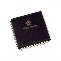
PIC16C74-20/L Microchip Technology, PIC16C74-20/L Datasheet - Page 279

PIC16C74-20/L
Manufacturer Part Number
PIC16C74-20/L
Description
MICRO CTRL 4K 20MHZ OTP 44PLCC
Manufacturer
Microchip Technology
Series
PIC® 16Cr
Datasheet
1.PIC16C72-04SO.pdf
(289 pages)
Specifications of PIC16C74-20/L
Core Processor
PIC
Core Size
8-Bit
Speed
20MHz
Connectivity
I²C, SPI, UART/USART
Peripherals
POR, PWM, WDT
Number Of I /o
33
Program Memory Size
7KB (4K x 14)
Program Memory Type
OTP
Ram Size
192 x 8
Voltage - Supply (vcc/vdd)
4 V ~ 6 V
Data Converters
A/D 8x8b
Oscillator Type
External
Operating Temperature
0°C ~ 70°C
Package / Case
44-PLCC
For Use With
DVA16XL441 - ADAPTER DEVICE ICE 44PLCC
Lead Free Status / RoHS Status
Request inventory verification / Request inventory verification
Eeprom Size
-
Available stocks
Company
Part Number
Manufacturer
Quantity
Price
Company:
Part Number:
PIC16C74-20/L
Manufacturer:
MICOCHIP
Quantity:
5 510
Company:
Part Number:
PIC16C74-20/L
Manufacturer:
TI
Quantity:
5 510
- Current page: 279 of 289
- Download datasheet (3Mb)
U
UA ................................................................................ 78, 83
Universal Synchronous Asynchronous Receiver Transmitter
(USART) ............................................................................ 99
Update Address bit, UA ............................................... 78, 83
USART
UV Erasable Devices ........................................................... 7
W
W Register
Wake-up from SLEEP ...................................................... 145
Watchdog Timer (WDT) ........................... 129, 133, 136, 144
WCOL .......................................................................... 79, 84
WDT ................................................................................. 136
Word ................................................................................ 129
WR pin ............................................................................... 54
Write Collision Detect bit, WCOL ................................. 79, 84
X
XMIT_MODE ...................................................................... 98
Z
Z bit .................................................................................... 30
Zero bit ................................................................................. 9
1997 Microchip Technology Inc.
Asynchronous Mode ................................................ 106
Asynchronous Receiver ........................................... 108
Asynchronous Reception ......................................... 109
Asynchronous Transmission .................................... 107
Asynchronous Transmitter ....................................... 106
Baud Rate Generator (BRG) .................................... 101
Receive Block Diagram ............................................ 108
Sampling .................................................................. 104
Synchronous Master Mode ...................................... 110
Synchronous Master Reception ............................... 112
Synchronous Master Transmission .......................... 110
Synchronous Slave Mode ........................................ 114
Synchronous Slave Reception ................................. 114
Synchronous Slave Transmit ................................... 114
Transmit Block Diagram ........................................... 106
ALU .............................................................................. 9
Block Diagram .......................................................... 144
Period ....................................................................... 144
Programming Considerations .................................. 144
Timeout .................................................................... 136
LIST OF EXAMPLES
Example 3-1:
Example 4-1:
Example 4-2:
Example 5-1:
Example 5-2:
Example 5-3:
Example 5-4:
Example 7-1:
Example 7-2:
Example 8-1:
Example 10-1: Changing Between Capture
Example 10-2: PWM Period and Duty Cycle
Example 11-1: Loading the SSPBUF (SSPSR)
Example 11-2: Loading the SSPBUF (SSPSR)
Example 12-1: Calculating Baud Rate Error ....................101
Equation 13-1: A/D Minimum Charging Time...................120
Example 13-1: Calculating the Minimum Required
Example 13-2: A/D Conversion........................................122
Example 13-3: 4-bit vs. 8-bit Conversion Times ..............123
Example 14-1: Saving STATUS, W, and PCLATH
Instruction Pipeline Flow............................17
Call of a Subroutine in Page 1
Indirect Addressing ....................................41
Initializing PORTA......................................43
Initializing PORTB......................................45
Initializing PORTC .....................................48
Read-Modify-Write Instructions
on an I/O Port ............................................53
Changing Prescaler (Timer0 WDT).........63
Changing Prescaler (WDT Timer0).........63
Reading a 16-bit Free-Running Timer .......67
Calculation .................................................75
Registers in RAM.....................................143
from Page 0 ..............................................41
Prescalers.................................................73
Register ....................................................80
Register (PIC16C76/77) ...........................85
Acquisition Time .....................................120
PIC16C7X
DS30390E-page 279
Related parts for PIC16C74-20/L
Image
Part Number
Description
Manufacturer
Datasheet
Request
R

Part Number:
Description:
MICRO CTRL 4K 4MHZ OTP 44PLCC
Manufacturer:
Microchip Technology
Datasheet:

Part Number:
Description:
MICRO CTRL 4K 20MHZ OTP 40DIP
Manufacturer:
Microchip Technology
Datasheet:

Part Number:
Description:
MICRO CTRL 4K 10MHZ OTP ET 40DIP
Manufacturer:
Microchip Technology
Datasheet:

Part Number:
Description:
MICRO CTRL 4K 10MHZ OTP 40DIP
Manufacturer:
Microchip Technology
Datasheet:

Part Number:
Description:
MICRO CTRL 4K 4MHZ OTP 40DIP
Manufacturer:
Microchip Technology
Datasheet:

Part Number:
Description:
MICRO CTRL 4K 4MHZ OTP 40DIP
Manufacturer:
Microchip Technology
Datasheet:

Part Number:
Description:
MICRO CTRL 4K 20MHZ EPROM 40CDIP
Manufacturer:
Microchip Technology
Datasheet:

Part Number:
Description:
8-Bit CMOS Microcontrollers with A/D Converter
Manufacturer:
Microchip Technology

Part Number:
Description:
8-Bit CMOS Microcontrollers with A/D Converter
Manufacturer:
Microchip Technology

Part Number:
Description:
8-Bit CMOS Microcontrollers with A/D Converter
Manufacturer:
Microchip Technology

Part Number:
Description:
8-Bit CMOS Microcontrollers with A/D Converter
Manufacturer:
Microchip Technology

Part Number:
Description:
8-Bit CMOS Microcontrollers with A/D Converter
Manufacturer:
Microchip Technology

Part Number:
Description:
8-Bit CMOS Microcontrollers with A/D Converter
Manufacturer:
Microchip Technology

Part Number:
Description:
8-Bit CMOS Microcontrollers with A/D Converter
Manufacturer:
Microchip Technology

Part Number:
Description:
8-Bit CMOS Microcontrollers with A/D Converter
Manufacturer:
Microchip Technology


