PIC16C770/JW Microchip Technology, PIC16C770/JW Datasheet - Page 65
PIC16C770/JW
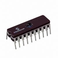
Manufacturer Part Number
PIC16C770/JW
Description
IC MCU EPROM2KX14 A/D PWM 20CDIP
Manufacturer
Microchip Technology
Series
PIC® 16Cr
Datasheets
1.PIC16C770-ISO.pdf
(220 pages)
2.PIC16C770-ISO.pdf
(6 pages)
3.PIC16C770-ISO.pdf
(8 pages)
Specifications of PIC16C770/JW
Core Processor
PIC
Core Size
8-Bit
Speed
20MHz
Connectivity
I²C, SPI
Peripherals
Brown-out Detect/Reset, POR, PWM, WDT
Number Of I /o
15
Program Memory Size
3.5KB (2K x 14)
Program Memory Type
EPROM, UV
Ram Size
256 x 8
Voltage - Supply (vcc/vdd)
4 V ~ 5.5 V
Data Converters
A/D 6x12b
Oscillator Type
Internal
Operating Temperature
0°C ~ 70°C
Package / Case
20-CDIP (0.300", 7.62mm) Window
For Use With
DVA16XP200 - ADAPTER ICE 20DIP/SOIC/SSOPAC164028 - MODULE SKT PROMATEII 20SOIC/DIP
Lead Free Status / RoHS Status
Contains lead / RoHS non-compliant
Eeprom Size
-


Note that in the Full-Bridge Output mode, the ECCP
module does not provide any deadband delay. In gen-
eral, since only one output is modulated at a time,
deadband delay is not required. However, there is a sit-
uation where a deadband delay might be required. This
situation occurs when all of the following conditions are
true:
1.
2.
Figure 8-11 shows an example, where the PWM direc-
tion changes from forward to reverse at a near 100%
duty cycle. At time t1, the output P1A and P1D become
inactive, while output P1C becomes active. In this
FIGURE 8-11: PWM DIRECTION CHANGE AT NEAR 100% DUTY CYCLE
2002 Microchip Technology Inc.
The direction of the PWM output changes when
the duty cycle of the output is at or near 100%.
The turn off time of the power switch, including
the power device and driver circuit, is greater
than turn on time.
Note 1: All signals are shown as active high.
External Switch C
External Switch D
2: t
3: t
Potential
Shoot Through
Current
on
off
is the turn on delay of power switch and driver.
is the turn off delay of power switch and driver.
P1C
P1D
P1A 1 0
P1B
1
0
1
0
1
0
1
0
1
0
1
0
(PWM)
FORWARD PERIOD
example, since the turn off time of the power devices is
longer than the turn on time, a shoot-through current
flows through the power devices, QB and QD, for the
duration of t= t
to power devices, QC and QB, for PWM direction
change from reverse to forward.
If changing PWM direction at high duty cycle is required
for the user’s application, one of the following require-
ments must be met:
1.
2.
PIC16C717/770/771
Avoid changing PWM output direction at or near
100% duty cycle.
Use switch drivers that compensate for the slow
turn off of the power devices. The total turn off
time (t
must be less than the turn on time (t
t
1
off
) of the power device and the driver
(PWM)
off
-t
t
on
on
. The same phenomenon will occur
REVERSE PERIOD
t
t = t
off
off
- t
on
DS41120B-page 63
on
).
Related parts for PIC16C770/JW
Image
Part Number
Description
Manufacturer
Datasheet
Request
R

Part Number:
Description:
IC MCU OTP 8KX14 A/D PWM 44PLCC
Manufacturer:
Microchip Technology
Datasheet:
Part Number:
Description:
IC MCU OTP 8KX14 A/D PWM 44PLCC
Manufacturer:
Microchip Technology
Datasheet:

Part Number:
Description:
IC MCU OTP 8KX14 A/D PWM 44TQFP
Manufacturer:
Microchip Technology
Datasheet:

Part Number:
Description:
IC MCU OTP 8KX14 A/D PWM 44-MQFP
Manufacturer:
Microchip Technology
Datasheet:

Part Number:
Description:
IC MCU OTP 8KX14 A/D PWM 40DIP
Manufacturer:
Microchip Technology
Datasheet:
Part Number:
Description:
IC MCU OTP 8KX14 A/D PWM 44PLCC
Manufacturer:
Microchip Technology
Datasheet:
Part Number:
Description:
IC MCU OTP 8KX14 A/D PWM 40DIP
Manufacturer:
Microchip Technology
Datasheet:
Part Number:
Description:
IC MCU OTP 8KX14 A/D PWM 40DIP
Manufacturer:
Microchip Technology
Datasheet:
Part Number:
Description:
IC MCU OTP 8KX14 A/D PWM 40DIP
Manufacturer:
Microchip Technology
Datasheet:
Part Number:
Description:
IC MCU OTP 8KX14 A/D PWM 44PLCC
Manufacturer:
Microchip Technology
Datasheet:
Part Number:
Description:
IC MCU OTP 8KX14 A/D PWM 44PLCC
Manufacturer:
Microchip Technology
Datasheet:
Part Number:
Description:
IC MCU OTP 8KX14 A/D PWM 44-MQFP
Manufacturer:
Microchip Technology
Datasheet:
Part Number:
Description:
IC MCU OTP 8KX14 A/D PWM 40DIP
Manufacturer:
Microchip Technology
Datasheet:
Part Number:
Description:
IC MCU OTP 8KX14 A/D PWM 44-MQFP
Manufacturer:
Microchip Technology
Datasheet:
Part Number:
Description:
IC MCU OTP 8KX14 A/D PWM 40DIP
Manufacturer:
Microchip Technology
Datasheet: