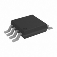
AD8021ARMZ Analog Devices Inc, AD8021ARMZ Datasheet - Page 21

AD8021ARMZ
Manufacturer Part Number
AD8021ARMZ
Description
IC OPAMP VF LN LP LDIST 8MSOP
Manufacturer
Analog Devices Inc
Specifications of AD8021ARMZ
Slew Rate
460 V/µs
Design Resources
Driving the AD7366/7 Bipolar SAR ADC in Low-Distortion DC-Coupled Appls (CN0042)
Amplifier Type
Voltage Feedback
Number Of Circuits
1
-3db Bandwidth
560MHz
Current - Input Bias
7.5µA
Voltage - Input Offset
400µV
Current - Supply
7.8mA
Current - Output / Channel
70mA
Voltage - Supply, Single/dual (±)
4.5 V ~ 24 V, ±2.25 V ~ 12 V
Operating Temperature
-40°C ~ 85°C
Mounting Type
Surface Mount
Package / Case
8-MSOP, Micro8™, 8-uMAX, 8-uSOP,
Op Amp Type
High Speed
No. Of Amplifiers
1
Bandwidth
560MHz
Supply Voltage Range
± 2.25V To ± 12V
Amplifier Case Style
MSOP
No. Of Pins
8
Common Mode Rejection Ratio
-98
Current, Input Bias
7.5 μA
Current, Input Offset
±0.1 μA
Current, Output
60 mA
Current, Supply
6.7 mA
Harmonic Distortion
-108 dBc
Impedance, Thermal
145 °C/W
Package Type
MSOP-8
Power Dissipation
34 mW
Resistance, Input
10 Megohms
Temperature, Operating, Range
-40 to +85 °C
Voltage, Input
-4.1 to +4.6 V (Common-Mode)
Voltage, Noise
2.1 nV/sqrt Hz
Voltage, Offset
0.4 mV
Voltage, Output, High
+3.4 V
Voltage, Output, Low
-3.8 V
Voltage, Supply
±5 V
Lead Free Status / RoHS Status
Lead free / RoHS Compliant
Output Type
-
Gain Bandwidth Product
-
Lead Free Status / Rohs Status
RoHS Compliant part
Electrostatic Device
Available stocks
Company
Part Number
Manufacturer
Quantity
Price
Company:
Part Number:
AD8021ARMZ
Manufacturer:
AD
Quantity:
8 469
Part Number:
AD8021ARMZ
Manufacturer:
ADI/亚德诺
Quantity:
20 000
Company:
Part Number:
AD8021ARMZ-REEL7
Manufacturer:
ALLEGRO
Quantity:
1 800
Part Number:
AD8021ARMZ-REEL7
Manufacturer:
ADI原装
Quantity:
20 000
THEORY OF OPERATION
The AD8021 is fabricated on the second generation of Analog
Devices proprietary High Voltage eXtra-Fast Complementary
Bipolar (XFCB) process, which enables the construction of PNP
and NPN transistors with similar f
transistors are dielectrically isolated from the substrate (and
each other), eliminating the parasitic and latch-up problems
caused by junction isolation. It also reduces nonlinear capaci-
tance (a source of distortion) and allows a higher transistor, f
for a given quiescent current. The supply current is trimmed,
which results in less part-to-part variation of bandwidth, slew
rate, distortion, and settling time.
As shown in Figure 61, the AD8021 input stage consists of an
NPN differential pair in which each transistor operates at a
0.8 mA collector current. This allows the input devices a high
transconductance; thus, the AD8021 has a low input noise of
2.1 nV/√Hz @ 50 kHz. The input stage drives a folded cascode
that consists of a pair of PNP transistors. The folded cascode
and current mirror provide a differential-to-single-ended
conversion of signal current. This current then drives the high
impedance node (Pin 5), where the C
connected. The output stage preserves this high impedance with
a current gain of 5000, so that the AD8021 can maintain a high
open-loop gain even when driving heavy loads.
Two internal diode clamps across the inputs (Pin 2 and Pin 3)
protect the input transistors from large voltages that could
otherwise cause emitter-base breakdown, which would result in
degradation of offset voltage and input bias current.
+IN
–IN
Figure 61. Simplified Schematic
C
1.5pF
INTERNAL
C
COMP
T
s in the 3 GHz region. The
C
external capacitor is
C
C
OUTPUT
+V
–V
S
S
Rev. F | Page 21 of 28
T
,
PCB LAYOUT CONSIDERATIONS
As with all high speed op amps, achieving optimum performance
from the AD8021 requires careful attention to PC board layout.
Particular care must be exercised to minimize lead lengths
between the ground leads of the bypass capacitors and between
the compensation capacitor and the negative supply. Otherwise,
lead inductance can influence the frequency response and even
cause high frequency oscillations. Use of a multilayer printed
circuit board, with an internal ground plane, reduces ground
noise and enables a compact component arrangement.
Due to the relatively high impedance of Pin 5 and low values of
the compensation capacitor, a guard ring is recommended. The
guard ring is simply a PC trace that encircles Pin 5 and is
connected to the output, Pin 6, which is at the same potential as
Pin 5. This serves two functions. It shields Pin 5 from any local
circuit noise generated by surrounding circuitry. It also
minimizes stray capacitance, which would tend to otherwise
reduce the bandwidth. An example of a guard ring layout is
shown in Figure 62.
Also shown in Figure 62, the compensation capacitor is located
immediately adjacent to the edge of the AD8021 package, spanning
Pin 4 and Pin 5. This capacitor must be a high quality surface-
mount COG or NPO ceramic. The use of leaded capacitors is
not recommended. The high frequency bypass capacitor(s)
should be located immediately adjacent to the supplies,
Pin 4 and Pin 7.
To achieve the shortest possible lead length at the inverting
input, the feedback resistor R
spans the distance from the output, Pin 6, to inverting input
Pin 2. The return node of Resistor R
as possible to the return node of the negative supply bypass
capacitor connected to Pin 4.
LOGIC REFERENCE
CAPACITOR
BYPASS
METAL
–V
–IN
+IN
S
Figure 62. Recommended Location of
Critical Components and Guard Ring
GROUND
PLANE
1
2
3
4
(TOP VIEW)
COMPENSATION
F
CAPACITOR
is located beneath the board and
+V
S
G
7
6
5
8
should be situated as close
DISABLE
C
COMP
V
OUT
GROUND
PLANE
BYPASS
CAPACITOR
AD8021


