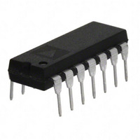
OP490GPZ Analog Devices Inc, OP490GPZ Datasheet - Page 10

OP490GPZ
Manufacturer Part Number
OP490GPZ
Description
IC OPAMP GP 20KHZ QUAD 14DIP
Manufacturer
Analog Devices Inc
Specifications of OP490GPZ
Slew Rate
0.012 V/µs
Amplifier Type
General Purpose
Number Of Circuits
4
Gain Bandwidth Product
20kHz
Current - Input Bias
4.2nA
Voltage - Input Offset
600µV
Current - Supply
60µA
Voltage - Supply, Single/dual (±)
1.6 V ~ 36 V, ±0.8 V ~ 18 V
Operating Temperature
-40°C ~ 85°C
Mounting Type
Through Hole
Package / Case
14-DIP (0.300", 7.62mm)
Op Amp Type
General Purpose
No. Of Amplifiers
4
Bandwidth
20kHz
Supply Voltage Range
± 0.8V To ± 18V
Amplifier Case Style
DIP
No. Of Pins
14
Channel Separation
150
Common Mode Rejection Ratio
120
Current, Input Bias
4.2 nA
Current, Input Offset
0.4 nA
Current, Supply
60 μA
Impedance, Thermal
33 °C/W
Number Of Amplifiers
Quad
Package Type
PDIP-14
Resistance, Input
30 Megohms (Differential), 20 Gigaohms (Common-Mode)
Temperature, Operating, Range
-40 to +85 °C
Voltage, Gain
800 V/mV
Voltage, Input
-15/13.5 V
Voltage, Noise
3 μV
Voltage, Offset
0.6 mV
Voltage, Output, High
4.2 V
Voltage, Output, Low
100 μV
Voltage, Supply
±15 V
Lead Free Status / RoHS Status
Lead free / RoHS Compliant
Output Type
-
Current - Output / Channel
-
-3db Bandwidth
-
Lead Free Status / Rohs Status
RoHS Compliant part
Electrostatic Device
OP490
INPUT VOLTAGE PROTECTION
The OP490 uses a PNP input stage with protection resistors in
series with the inverting and noninverting inputs. The high
breakdown of the PNP transistors coupled with the protection
resistors provides a large amount of input protection, allowing
the inputs to be taken 20 V beyond either supply without
damaging the amplifier.
MICROPOWER VOLTAGE-CONTROLLED
OSCILLATOR
An OP490 in combination with an inexpensive quad CMOS
switch comprise the precision V
provides triangle and square wave outputs and draws only 75 μA
from a 5 V supply. A acts as an integrator; S1 switches the
V
CONTROL
200kΩ
200kΩ
R1
R2
100kΩ
R3
CO
2
3
4
5
6
7
1
of Figure 22. This circuit
R4
200kΩ
IN/OUT
IN/OUT
CONT
CONT
V
OUT/IN
OUT/IN
SS
2
3
–
OP490
+
1/4
+15V
A
75nF
C1
11
4
Figure 22. Micropower Voltage Controlled Oscillator
S1
S2
S3
S4
1
Rev. E | Page 10 of 16
IN/OUT
OUT/IN
OUT/IN
IN/OUT
TRIANGLE
CONT
CONT
V
OUT
DD
14
13
12
11
10
9
8
+5V
charging current symmetrically to yield positive and negative
ramps. The integrator is bounded by B, which acts as a Schmitt
trigger with a precise hysteresis of 1.67 V, set by Resistors R5,
R6, and R7, and the associated CMOS switches. The resulting
output of A is a triangle wave with upper and lower levels of
3.33 V and 1.67 V. The output of B is a square wave with almost
rail-to-rail swing. With the components shown, frequency of
operation is given by the equation
but this is easily changed by varying C1. The circuit operates
well up to a few hundred hertz.
+5V
f
OUT
200kΩ
R8
= V
CONTROL
+5V
200kΩ
200kΩ
R5
R6
+15V
(Volts) × 10 Hz/V
6
5
–
+
OP490
R7
200kΩ
1/4
B
7
SQUARE
OUT


