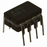
HA7-2520-2 Intersil, HA7-2520-2 Datasheet - Page 4

HA7-2520-2
Manufacturer Part Number
HA7-2520-2
Description
IC OPAMP 20MHZ 120V/US 8-DIP
Manufacturer
Intersil
Datasheet
1.HA3-2525-5.pdf
(12 pages)
Specifications of HA7-2520-2
Amplifier Type
General Purpose
Number Of Circuits
1
Slew Rate
120 V/µs
Gain Bandwidth Product
20MHz
Current - Input Bias
100nA
Voltage - Input Offset
4000µV
Current - Supply
4mA
Current - Output / Channel
20mA
Voltage - Supply, Single/dual (±)
8 V ~ 36 V, ±4 V ~ 18 V
Operating Temperature
-55°C ~ 125°C
Mounting Type
Through Hole
Package / Case
8-CDIP (0.300", 7.62mm)
Lead Free Status / RoHS Status
Contains lead / RoHS non-compliant
Output Type
-
-3db Bandwidth
-
Available stocks
Company
Part Number
Manufacturer
Quantity
Price
Test Circuits and Waveforms
NOTE: Tested offset adjustment range is |V
FIGURE 3. SLEW RATE AND TRANSIENT RESPONSE
IN
OUTPUT
FIGURE 1. SLEW RATE AND SETTLING TIME
INPUT
-1.67V
-5V
+5V
+1.67V
+
-
75%
25%
5pF
Δt
SETTLING
TIME
FIGURE 5. SUGGESTED V
4
ΔV
SLEW
RATE
= ΔV/Δt
1333Ω
667Ω
OS
ERROR BAND
±10mV FROM
FINAL VALUE
+ 1mV| minimum referred to output. Typical ranges are ±20mV with R
HA-2520, HA-2522, HA-2525
50pF
IN
OUT
OS
V+
ADJUSTMENT AND COMPENSATION HOOK-UP
BAL.
V-
20kΩ
NOTE: Measured on both positive and negative transitions from 0V
to +200mV and 0V to -200mV at the output.
NOTES:
17. A
18. Feedback and summing resistor ratios should be 0.1% matched.
19. Clipping diodes CR
COMP
C
C
2N4416
2000Ω
recommended.
V
= -3.
0V
OUT
OUTPUT
±200mV
D
S
FIGURE 4. SETTLING TIME TEST CIRCUIT
INPUT
G
90%
10%
CR
FIGURE 2. TRANSIENT RESPONSE
INPUT
±67mV
0V
1
667.2Ω
1667Ω
OVERSHOOT
1
and CR
CR
RISE TIME
2
SETTLING TIME
TEST POINT
2
3
V+
2
-
+
7
are optional. HP5082-2810
V-
4
6
T
0.001
0.001
= 20kΩ.
1
4999.9Ω
2001Ω
1F
µ
F
µ
µ
F
F
February 16, 2009
OUTPUT
100pF
FN2894.9


