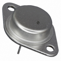
LM140K-5.0/NOPB National Semiconductor, LM140K-5.0/NOPB Datasheet - Page 11

LM140K-5.0/NOPB
Manufacturer Part Number
LM140K-5.0/NOPB
Description
IC VOLT REG POS 3 TERM 5V T0-3
Manufacturer
National Semiconductor
Datasheet
1.LM140K-5.0NOPB.pdf
(17 pages)
Specifications of LM140K-5.0/NOPB
Regulator Topology
Positive Fixed
Voltage - Output
5V
Voltage - Input
7.5 ~ 20 V
Voltage - Dropout (typical)
2V @ 1A
Number Of Regulators
1
Current - Output
1.5A
Current - Limit (min)
2.4A
Operating Temperature
-55°C ~ 125°C
Mounting Type
Through Hole
Package / Case
TO-204, TO-3
Voltage Regulator Type
Linear
Topology
Standard
Regulator Output Type
Fixed
Polarity Type
Positive
Number Of Outputs
Single
Input Voltage (min)
7.5V
Input Voltage (max)
35V
Output Voltage
5V
Package Type
TO-3
Output Current
2.4(Typ)A
Load Regulation
50mV
Line Regulation
50mV
Output Voltage Accuracy
±2%
Operating Temp Range
-55C to 125C
Operating Temperature Classification
Military
Dropout Voltage@current (typ)
2@1A
Pin Count
2 +Tab
Mounting
Through Hole
Quiescent Current (max)
6mA
Lead Free Status / RoHS Status
Lead free / RoHS Compliant
Other names
*LM140K-5.0
*LM140K-5.0/NOPB
LM140K-5.0
*LM140K-5.0/NOPB
LM140K-5.0
Application Hints
The LM340/LM78XX series is designed with thermal protec-
tion, output short-circuit protection and output transistor safe
area protection. However, as with any IC regulator, it be-
comes necessary to take precautions to assure that the
regulator is not inadvertently damaged. The following de-
scribes possible misapplications and methods to prevent
damage to the regulator.
SHORTING THE REGULATOR INPUT
When using large capacitors at the output of these regula-
tors, a protection diode connected input to output (Figure 1)
may be required if the input is shorted to ground. Without the
protection diode, an input short will cause the input to rapidly
approach ground potential, while the output remains near
the initial V
output capacitor. The capacitor will then discharge through a
large internal input to output diode and parasitic transistors.
If the energy released by the capacitor is large enough, this
diode, low current metal and the regulator will be destroyed.
The fast diode in Figure 1 will shunt most of the capacitors
discharge current around the regulator. Generally no protec-
tion diode is required for values of output capacitance ≤ 10
µF.
RAISING THE OUTPUT VOLTAGE ABOVE THE INPUT
VOLTAGE
Since the output of the device does not sink current, forcing
the output high can cause damage to internal low current
paths in a manner similar to that just described in the “Short-
ing the Regulator Input” section.
REGULATOR FLOATING GROUND (Figure 2)
When the ground pin alone becomes disconnected, the
output approaches the unregulated input, causing possible
damage to other circuits connected to V
reconnected with power “ON”, damage may also occur to the
regulator. This fault is most likely to occur when plugging in
regulators or modules with on card regulators into powered
up sockets. Power should be turned off first, thermal limit
ceases operating, or ground should be connected first if
power must be left on.
TRANSIENT VOLTAGES
If transients exceed the maximum rated input voltage of the
device, or reach more than 0.8V below ground and have
sufficient energy, they will damage the regulator. The solu-
tion is to use a large input capacitor, a series input break-
down diode, a choke, a transient suppressor or a combina-
tion of these.
OUT
because of the stored charge in the large
OUT
. If ground is
11
When a value for θ
a heatsink must be selected that has a value that is less than
or equal to this number.
θ
in this catalog, or shown in a curve that plots temperature
rise vs power dissipation for the heatsink.
(H–A)
is specified numerically by the heatsink manufacturer
FIGURE 2. Regulator Floating Ground
FIGURE 1. Input Short
FIGURE 3. Transients
(H–A)
is found using the equation shown,
www.national.com
00778109
00778110
00778108


