LP5952TL-1.2/NOPB National Semiconductor, LP5952TL-1.2/NOPB Datasheet
LP5952TL-1.2/NOPB
Specifications of LP5952TL-1.2/NOPB
LP5952TL-1.2TR
Available stocks


Related parts for LP5952TL-1.2/NOPB


LP5952TL-1.2/NOPB Summary of contents
Page 1
... The device is available in fixed output voltages in the range of 0.5V to 2.0V. For availability, please contact your local NSC sales office. Typical Application Circuit FIGURE 1. Typical Application Circuit with DC-DC Converter as Pre-Regulator for V © 2008 National Semiconductor Corporation Features ■ Excellent load transient response: ±15mV typical ■ ...
Page 2
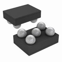
Connection Diagrams Connection Diagram 5-Bump Thin Micro SMD Package, Large Bump, 0.5mm Pitch www.national.com FIGURE 2. Typical Application Circuit 5-Bump Micro SMD Package See NS Package Number TLA05 Package Marking 20208506 2 20208502 20208503 ...
Page 3
... Enable pin logic input: low = shutdown, high = active, normal operation. EN This pin should not be left floating. Tie not make connections to this pin LP5952 Supplied as 3000 Units, Tape and Reel, lead free LP5952TLX-0.7 LP5952TLX-1.0 LP5952TLX-1.2 LP5952TLX-1.3 LP5952TLX-1.4 LP5952TLX-1.5 LP5952TLX-1.6 LP5952TLX-1.8 LP5952TLX-2.0 3 20208524 ≤ V ...
Page 4
Order Information (COL LLP-6) Output Voltage LP5952 Supplied as 1000 Units, (V) Tape and Reel, lead free 1.2 LP5952LC-1.2 1.3 LP5952LC-1.3 1.5 LP5952LC-1.5 1.8 LP5952LC-1.8 www.national.com LP5952 Supplied as 4500 Units, Tape and Reel, lead free LP5952LCX-1.2 LP5952LCX-1.3 LP5952LCX-1.5 LP5952LCX-1.8 ...
Page 5
... ESD Rating (Note 5): Human Body Model: Machine Model: ESD Caution Notice National Semiconductor recommends that all integrated circuits be handled with appropriate precautions. Failure to observe proper ESD handling techniques can result in damage. Electrical Characteristics Typical values and limits appearing in standard typeface are for T ≤ ...
Page 6
Symbol Parameter PSRR Power Supply Rejection Ratio Quiescent Currents Symbol Parameter I Current into V Q_VBATT BATT I Current into V Q_VIN IN Shutdown Currents Symbol Parameter I Current into V Q_VBATT BATT I Current into V Q_VIN IN Enable ...
Page 7
... Note 3: Internal thermal shutdown circuitry protects the device from permanent damage. Thermal shutdown engages 145°C (typ.). Note 4: For detailed soldering specifications and information, please refer to National Semiconductor Application Note 1112: Micro SMD Wafer Level Chip Scale Package (AN-1112) and Application Note 1187: Leadless Leadframe Package (LLP) (AN-1187). ...
Page 8
Block Diagram www.national.com 20208505 8 ...
Page 9
Typical Performance Characteristics ceramic 1V OUT(NOM) BATT Load Transient Response, 0.7V Option Line Transient Response V IN Enable Start-up Time, 0.7V Option Unless otherwise specified 1.5V 25°C, Enable ...
Page 10
Output Voltage Change vs Temperature Inrush Current V , 1.5V Option IN Ground Current vs V www.national.com Dropout V 20208515 Quiescent Current I 20208517 / V BATT IN 20208519 10 vs Temperature 350mA IN LOAD 20208516 vs V ...
Page 11
Power Supply Rejection Ratio V Application Hints DUAL RAIL SUPPLY The LP5952 requires two different supply voltages: •V , the power input voltage, is regulated to the fixed output IN voltage •V , the bias input voltage, supplies internal circuitry. ...
Page 12
INPUT CAPACITOR If the LP5952 is used stand alone, an input capacitor at V required for stability recommended that a 1.0µF capacitor be connected between the LP5952 power voltage input pin V and ground (this capacitance value may ...
Page 13
ENABLE OPERATION The LP5952 may be switched ON or OFF by a logic input at the Enable pin logic high at this pin will turn the device EN on. When the enable pin is low, the regulator ...
Page 14
Physical Dimensions For most accurate revision please refer to www.national.com/packaging/parts/ www.national.com inches (millimeters) unless otherwise noted NS Package Number TLA05Z1A X1 = 955 µm ±30µ 1335µm ±30µ 600µm ±75µm 5-Bump Thin Micro SMD Package, Large Bump ...
Page 15
Notes 15 www.national.com ...
Page 16
... For more National Semiconductor product information and proven design tools, visit the following Web sites at: Products Amplifiers www.national.com/amplifiers Audio www.national.com/audio Clock Conditioners www.national.com/timing Data Converters www.national.com/adc Displays www.national.com/displays Ethernet www.national.com/ethernet Interface www.national.com/interface LVDS www.national.com/lvds Power Management www.national.com/power Switching Regulators www.national.com/switchers LDOs www ...