TR250-145U Tyco Electronics, TR250-145U Datasheet - Page 2
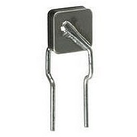
TR250-145U
Manufacturer Part Number
TR250-145U
Description
POLYSWITCH 0.145A HOLD UNENCAPS
Manufacturer
Tyco Electronics
Series
PolySwitch®r
Datasheet
1.TR250-145.pdf
(28 pages)
Specifications of TR250-145U
R Min/max
3.500 ~ 6.500 Ohm
Voltage - Max
60V
Time To Trip
2s
Current - Hold (ih) (max)
145mA
Current - Trip (it)
290mA
Current - Max
3A
Package / Case
Radial
Holding Current
0.145A
Tripping Current
0.29A
Initial Resistance Max
6.5ohm
Initial Resistance Min
3.5ohm
Resistance R1
12ohm
Peak Reflow Compatible (260 C)
No
Fuse Terminals
Radial Leaded
Thermistor Type
PTC
Lead Free Status / RoHS Status
Contains lead / RoHS non-compliant
Other names
TR145U
Available stocks
Company
Part Number
Manufacturer
Quantity
Price
Company:

Part Number:
TR250-145U
Manufacturer:
Raychem
Quantity:
190
Company:
Part Number:
TR250-145US
Manufacturer:
MOLEX
Quantity:
32 648


4
302
Selection Table for Telecommunications and Networking Devices
PolySwitch Telecommunications and Networking Resettable Devices
Step 1.
Use the selection guide to narrow your product selection based on key
device characteristics.
Step 2.
Look across the top of the thermal derating table T2 on page 306 to
find the temperature that most closely matches the circuit’s maximum
operating temperature. Look down that column to find the value equal
to or greater than the circuit’s normal operating current. Now look to the
far left of that row to find the part number for the PolySwitch telecom-
munications device that will best accommodate the circuit.
Note: The thermal derating curves in Figure T1 on page 307 are the
normalized representations of the data in the thermal derating table.
Step 3.
Time-to-trip is the amount of time it takes for a device to switch to a
high resistance state once a fault current has been applied across the
device. Identifying the PolySwitch device’s time-to-trip is important in
order to provide the desired protection capabilities. If the device you
choose trips too fast, undesired or nuisance tripping will occur. If the
device trips too slowly, the components being protected may be
damaged before the device switches to a high resistance state.
Refer to typical time-to-trip curves (Figures T12-17) on pages 313-315
for each of the PolySwitch devices. If the PolySwitch device’s time-to-
trip is too fast or too slow for the circuit, go back to Step 2 and choose
an alternate device.
Step 4.
Ensure that your application’s minimum and maximum ambient
temperatures are within the operating temperature range of -40°C
to 85°C.
Step 5.
PolySwitch devices assist your telecommunications equipment in meet-
ing agency requirements. To confirm your selection, independently
evaluate and test the device to the application requirements.
Review the Protection Application Guide on page 303
which is based on the agency specification required to
qualify the final equipment.
Verify that the PolySwitch device hold current will accom-
modate the telecommunications circuit’s maximum ambi-
ent temperature and normal operating current.
Verify that the time-to-trip characteristic of the chosen
device meets the protection requirements of the
telecommunications equipment circuit.
Verify ambient operating condition.
Independently evaluate and test the device.
Raychem Circuit Protection
Related parts for TR250-145U
Image
Part Number
Description
Manufacturer
Datasheet
Request
R

Part Number:
Description:
PTC Resettable Fuses TR250-120S-1
Manufacturer:
Tyco Electronics
Part Number:
Description:
PTC Resettable Fuses TR250-120US-1
Manufacturer:
Tyco Electronics

Part Number:
Description:
POLYSWITCH 0.120A HOLD ENCAPSUL
Manufacturer:
Tyco Electronics
Datasheet:

Part Number:
Description:
POLYSWITCH 0.145A HOLD ENCAPSUL
Manufacturer:
Tyco Electronics
Datasheet:
Part Number:
Description:
POLYSWITCH 0.145A HOLD ENCAPSUL
Manufacturer:
Tyco Electronics
Part Number:
Description:
FUSE, PTC RESET, 250V, 180mA, RADIAL
Manufacturer:
Tyco Electronics
Part Number:
Description:
PTC Resettable Fuses TR250-120U-B-0.5-2
Manufacturer:
Tyco Electronics
Part Number:
Description:
PTC Resettable Fuses TR250-145US-2
Manufacturer:
Tyco Electronics
Part Number:
Description:
PTC Resettable Fuses TR250-090-2
Manufacturer:
Tyco Electronics
Part Number:
Description:
Manufacturer:
Tyco Electronics
Datasheet: