V180MT1A Littelfuse Inc, V180MT1A Datasheet - Page 3
V180MT1A
Manufacturer Part Number
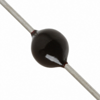
V180MT1A
Description
VARISTOR 180V .60J 3MM AXIAL T/R
Manufacturer
Littelfuse Inc
Datasheet
1.V220MA2A.pdf
(5 pages)
Specifications of V180MT1A
Varistor Voltage
180V
Current-surge
100A
Number Of Circuits
1
Maximum Ac Volts
105VAC
Maximum Dc Volts
144VDC
Energy
0.60J
Package / Case
Axial
Product
MOV
Voltage Rating Dc
144 V
Voltage Rating Ac
105 V
Clamping Voltage
310 V
Peak Surge Current
100 A
Capacitance
27 pF
Operating Temperature Range
- 55 C to + 85 C
Mounting
Radial
Dimensions
3 mm Dia.
Termination Style
Axial
Lead Free Status / RoHS Status
Lead free / RoHS Compliant
Lead Free Status / RoHS Status
Lead free / RoHS Compliant, Lead free / RoHS Compliant


V18MA - V100MA
©2008 Littelfuse, Inc.
Specifications are subject to change without notice.
Please refer to www.littelfuse.com/series/ma.html for current information.
Power Dissipation Ratings
Should transients occur in rapid succession, the average power
dissipation required is simply the energy (watt-seconds) per
pulse times the number of pulses per second. The power so
developed must be within the specifications shown on the
Device Ratings and Specifications table for the specific device.
Furthermore, the operating values need to be derated at high
temperatures as shown above. Because varistors can only
dissipate a relatively small amount of average power they are,
therefore, not suitable for repetitive applications that involve
substantial amounts of average power dissipation.
Repetitive Surge Capability
Figure 3
Figure 1
100
90
80
70
60
50
40
30
20
10
0
-55
0.5
0.2
0.1
50
20
10
5
2
1
20
10
10
10
1
2
10
50
INDEFINITE
2
3
4
60
100
AMBIENT TEMPERATURE (
70
IMPULSE DURATION (μs)
80
90
100 110
10
1,000
5
10
DISC SIZE 3mm
V18MA1A - V100MA4B
6
120 130 140 150
Varistor Products
o
Axial Lead / Application Specific Varistors > MA Series
C)
10,000
Revision: January 9, 2009
185
V120MA1A/S - V430MA3A
NOTE: If pulse ratings are exceeded, a shift of V
+/-10% could result. This type of shift, which normally results in a decrease of V
result in the device not meeting the original published specifications, but it does not
prevent the device from continuing to function, and to provide ample protection.
Peak Pulse Current Test Waveform
Figure 4
Figure 2
0
T = Time from 10% to 90% of Peak
T
T
Example - For an 8/20 μs Current Waveform:
100
1
1
2
0.5
0.2
0.1
50
20
10
= Virtual Origin of Wave
5
2
1
= Rise Time = 1.25 x T
= Decay Time
20
8μs = T
20μs = T
10
10
2
O
100
2
1
90
50
10
INDEFINITE
1
1
2
= Rise Time
= Decay Time
100
IMPULSE DURATION (μs)
T
T
1
T
2
N(DC)
10
10
3
10
(at specified current) of more than
4
10
5
DISC SIZE 3mm
V120MA1A - V430MA7B
6
1,000
TIME
MA Varistor Series
10,000
N(DC)
, may
Related parts for V180MT1A
Image
Part Number
Description
Manufacturer
Datasheet
Request
R

Part Number:
Description:
FUSEHOLDER 20A MINI INLINE CRIMP
Manufacturer:
Littelfuse Inc
Datasheet:

Part Number:
Description:
FUSEHOLDER BODY ATO INLINE PNLMT
Manufacturer:
Littelfuse Inc
Datasheet:

Part Number:
Description:
FUSE 2A 63V FAST 1206
Manufacturer:
Littelfuse Inc
Datasheet:
Part Number:
Description:
FUSE 1.25A 63V FAST 1206
Manufacturer:
Littelfuse Inc
Datasheet:
Part Number:
Description:
FUSE .250A 125V FAST 1206
Manufacturer:
Littelfuse Inc
Datasheet:
Part Number:
Description:
FUSE 4A 32V FAST 1206
Manufacturer:
Littelfuse Inc
Datasheet:
Part Number:
Description:
FUSE 1.75A 63V FAST 1206
Manufacturer:
Littelfuse Inc
Datasheet:

Part Number:
Description:
FUSE 1A 32V FST 0603 LEADFREE TR
Manufacturer:
Littelfuse Inc
Datasheet:

Part Number:
Description:
FUSE 1A 32V FAST SLIM 0402
Manufacturer:
Littelfuse Inc
Datasheet:

Part Number:
Description:
FUSE 2A 125V FAST NANO2 SMD
Manufacturer:
Littelfuse Inc
Datasheet:

Part Number:
Description:
FUSE .250A 125V FAST NANO2 SMD
Manufacturer:
Littelfuse Inc
Datasheet:

Part Number:
Description:
FUSE .500A 125V FAST NANO2 SMD
Manufacturer:
Littelfuse Inc
Datasheet:

Part Number:
Description:
FUSE 1.5A 125V FAST NANO2 SMD
Manufacturer:
Littelfuse Inc
Datasheet:

Part Number:
Description:
FUSE 4A 125V FAST NANO2 SMD
Manufacturer:
Littelfuse Inc
Datasheet:

Part Number:
Description:
FUSE 1A 125V FAST NANO2 SMD
Manufacturer:
Littelfuse Inc
Datasheet: