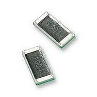
RC2512JK-070RL Yageo, RC2512JK-070RL Datasheet

RC2512JK-070RL
Specifications of RC2512JK-070RL
Available stocks
Related parts for RC2512JK-070RL
RC2512JK-070RL Summary of contents
Page 1
... DATA SHEET THICK FILM CHIP RESISTORS Introduction ...
Page 2
... Yageo thick film chip resistor is flameproof and can meet “UL94V-0”. ORDERING INFORMATION - 12NC & GLOBAL CLEAR TEXT CODE Resistors are ordered in two ways ...
Page 3
... X or 974 X at –55 °C: 1,000 X ±(80 × 200 ppm/°C) × 1,000 X = 1,016 X or 984 X If the temperature coefficient is specified as ≤200 ppm/°C the resistance will be within the shaded area as shown in Fig Ω Ω Product specification INTRODUCTION 155 MGA208 www.yageo.com 3 16 ...
Page 4
... Mar 25, 2008 V.7 Thick film technology INTRODUCTION Size 1206 36 noise level μ 100 Fig. 2 Typical noise levels as a function of rated resistance 4 Product specification 16 SCR028 100 Ω ) www.yageo.com ...
Page 5
... Chip Resistor Surface Mount Size 0402 2 1.6 1.2 0 MΩ Fig. 4 Impedance as a function of frequency for a chip resistor Mar 25, 2008 V.7 Thick film technology R = 100 kΩ kΩ Product specification INTRODUCTION SCR027 Ω Ω kΩ (Hz) www.yageo.com ...
Page 6
... MΩ 100 Fig. 6 Phase shift as a function of frequency for a chip resistor Mar 25, 2008 V.7 Thick film technology Ω 100 kΩ Ω 100 kΩ kΩ Product specification INTRODUCTION MLB716 Ω 100 Ω kΩ kΩ (Hz) MLB717 Ω 100 Ω kΩ (Hz) www.yageo.com ...
Page 7
... MΩ 100 Fig. 8 Phase shift as a function of frequency for a chip resistor Mar 25, 2008 V.7 Thick film technology Ω 100 kΩ kΩ Ω 100 kΩ kΩ Product specification INTRODUCTION MLB718 Ω 100 Ω kΩ (Hz) MLB719 Ω 100 Ω kΩ (Hz) www.yageo.com ...
Page 8
... MΩ 100 Fig. 10 Phase shift as a function of frequency for a chip resistor Mar 25, 2008 V.7 Thick film technology Ω Ω 100 kΩ kΩ Ω 100 kΩ kΩ Product specification INTRODUCTION MLB720 R = 100 Ω kΩ (Hz) MLB721 Ω 100 Ω kΩ (Hz) www.yageo.com ...
Page 9
... DIN IEC 60040 (CO) 533 max Product specification Table 1 Pulse load limits PARAMETER VALUE Exponential time constant 50 to 700 µs Repetition time Amount of pulses that may be applied in a regular way can be determined in a similar manner. MBD641 1.2/50 μs 10/700 μ (Ω) n www.yageo.com 9 16 ...
Page 10
... Fig. 13 Pulse on a regular basis; maximum permissible peak pulse voltage Mar 25, 2008 V.7 Thick film technology INTRODUCTION single pulse repetitive pulse ˆ function of pulse duration for R ≤ Ω , single pulse ) max ˆ function of pulse duration (t max Product specification MBC188 (s) i MBD586 ( www.yageo.com 10 16 ...
Page 11
... R dashed line of Fig. 12 for the applicable value ˆ must be lower than the value of − Fig. 13 for the applicable value Product specification ˆ given max / ˆ given max . i = 0.5 τ ˆ given by the max V ˆ given max . i www.yageo.com ...
Page 12
... The dashed curve of Fig. 12 shows that at t the permissible permissible YNSC059 used. t Product specification INTRODUCTION –5 – − and = = , 1 000 − – and , 1 000 , Fig. 12 gives ˆ = 400 V max V ˆ – 250 = . 000 P ˆ and Fig. 13 shows a max V ˆ of 400 V, so this resistor may be max www.yageo.com – ...
Page 13
... According to Yageo calculation, assuming components life time is following exponential distribution and using 60% confidence interval (60% C.I.) in Homogeneous Poisson Process; therefore the FIT is calculated by number of tested Failure in Endurance Test (rated power at 70°C for 1,000 hours, “IEC 60115-1 4.25.1” following: FIT Table 4 FIT of single resistor chips ...
Page 14
... Fig. 19 Typical percentage change in resistance after 56 days Product specification INTRODUCTION MGA214 spec. level 0 spec. level 1 10 100 100 (Ω) for 10 seconds at 270 °C, completely immersed MGA216 2 spec. level spec. level 100 100 (Ω °C and 90 to 95% relative humidity loaded with P nom www.yageo.com ...
Page 15
... R spec. level R 0.8 (%) 0.4 0 0.4 0.8 spec. level 1 100 Fig. 20 Typical percentage change in resistance after 1,000 hours loaded with °C ambient temperature nom Mar 25, 2008 V.7 Thick film technology MGA218 100 (Ω) Product specification INTRODUCTION www.yageo.com 15 16 ...
Page 16
... Thick film technology INTRODUCTION - Headline changes to Introduction Thick Film Chip Resistor - Add international standard and failures in time - Converted to Yageo / Phycomp brand - Separated “Marking” into an individual data sheet - Mechanical data extended from sizes 0201 to 2512, resistor arrays/network and attenuators as well - Impedance chart for size 0402 added ...


