E3X-NA11 Omron, E3X-NA11 Datasheet - Page 11
E3X-NA11
Manufacturer Part Number
E3X-NA11
Description
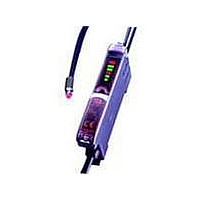
NPN GEN PURPOSE FO AMP
Manufacturer
Omron
Series
E3X-NAr
Type
Standard Fiber Optic Sensorr
Specifications of E3X-NA11
Output Type
NPN
Amplifier Type
Standard
Voltage - Supply
12 V ~ 24 V
Current - Supply
35mA
Mounting Type
DIN Rail
Sensor Output
NPN
Length/height, External
31.5mm
Sensor Housing
Rectangular
Sensor Input
Fiber Optic
External Width
10mm
Supply Voltage Max
24V
Switch Terminals
Wire Leaded
Supply Voltage Min
12V
Rohs Compliant
Yes
External Depth
64.3mm
Fiber Optic Sensor Type
Standard Fiber Optic Sensor
Lead Free Status / RoHS Status
Lead free / RoHS Compliant
Lead Free Status / RoHS Status
Lead free / RoHS Compliant, Lead free / RoHS Compliant
Other names
E3XNA11


I/O Circuit Diagrams
Note: Timing Charts for Timer Settings (T: Set Time)
Plug (Sensor I/O Connector)
Output
NPN
Output
PNP
Output
form
3
No incident light
4
Incident light
2
L-ON
D-ON
1
E3X-SD11
E3X-SD6
E3X-NA11
E3X-NA6
E3X-NA11F
E3X-NA11V
E3X-NA14V
E3X-SD41
E3X-SD8
E3X-NA41
E3X-NA8
E3X-NA41F
E3X-NA41V
E3X-NA44V
ON delay
OFF
OFF
ON
ON
Model
Terminal number
1
2
3
4
XS3F-M421-402-A
XS3F-M421-405-A
T
T
operation mode
transistor
Light-ON
Dark-ON
Light-ON
Dark-ON
Output
No incident light
Incident light
L-ON
D-ON
XS3F-M422-402-A
XS3F-M422-405-A
OFF delay
OFF
OFF
ON
ON
Operation
indicator
(orange)
Output
transistor
Load
(relay)
Operation
indicator
(orange)
Output
transistor
Load
(relay)
Operation
indicator
(orange)
Output
transistor
Load
(relay)
Operation
indicator
(orange)
Output
transistor
Load
(relay)
No incident light
No incident light
No incident light
No incident light
(Between brown and black leads)
(Between brown and black leads)
(Between blue and black leads)
(Between blue and black leads)
T
Incident light
Incident light
Incident light
Incident light
Wire color
Timing charts
Operate
Operate
Operate
Operate
T
Reset
Reset
Reset
Reset
OFF
OFF
OFF
OFF
Brown
White
Blue
Black
OFF
OFF
OFF
OFF
ON
ON
ON
ON
ON
ON
ON
ON
T
T
T
T
Note: Pin 2 is not used.
Classification
DC
Operation
LIGHT ON
LIGHT ON
DARK ON
DARK ON
selector
(D-ON)
(D-ON)
(L-ON)
(L-ON)
Wire color
Brown
White
Black
Blue
• M8 Connector Pin Arrangement
Note: Pin 2 is not used.
• M8 Connector Pin Arrangement
Note: Pin 2 is not used.
Operation
indicator
(orange)
Operation indicator
(orange)
Photo-
electric
Sensor
main
circuit
Photo-
electric
Sensor
main
circuit
Connection pin
1
2
3
4
Output circuit
*Not present on the E3X-NA.
*Not present on the E3X-NA.
*
*
Power supply (0 V)
Power supply (+V)
1
1
E3X-SD/-NA
1
4
3
1
4
3
2
2
Blue
Brown
Black
Blue
Brown
Black
Application
4
4
3
3
Output
Control output
---
Control output
Load
Load
12 to
24 VDC
12 to
24 VDC
11
Related parts for E3X-NA11
Image
Part Number
Description
Manufacturer
Datasheet
Request
R

Part Number:
Description:
SENSOR PHOTOAMP FIBER 2M CBL
Manufacturer:
Omron
Datasheet:

Part Number:
Description:
CONN READY NPN GEN PURPOSE FO
Manufacturer:
Omron
Datasheet:
Part Number:
Description:
CONN READY PNP GEN PURPOSE FO
Manufacturer:
Omron
Datasheet:
Part Number:
Description:
PNP GREEN LED GEN PURPOSE FOA
Manufacturer:
Omron
Datasheet:
Part Number:
Description:
AMANUAL FA NPN RED M8 CONN
Manufacturer:
Omron
Datasheet:

Part Number:
Description:
PNP GEN PURPOSE FO AMP
Manufacturer:
Omron
Datasheet:

Part Number:
Description:
AUTOTUNE NPN
Manufacturer:
Omron
Datasheet:
Part Number:
Description:
AUTOTUNE NPN TMR REMOTE TCH
Manufacturer:
Omron
Datasheet:
Part Number:
Description:
AUTOTUNE PNP TMR REMOTE TCH
Manufacturer:
Omron
Datasheet:

Part Number:
Description:
PREWIRED DIGITAL NPN FO AMP
Manufacturer:
Omron
Datasheet:

Part Number:
Description:
G6S-2GLow Signal Relay
Manufacturer:
Omron Corporation
Datasheet:
Part Number:
Description:
Compact, Low-cost, SSR Switching 5 to 20 A
Manufacturer:
Omron Corporation
Datasheet:
Part Number:
Description:
Manufacturer:
Omron Corporation
Datasheet: