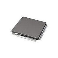
71M6513-IGT/F Maxim Integrated Products, 71M6513-IGT/F Datasheet - Page 44

71M6513-IGT/F
Manufacturer Part Number
71M6513-IGT/F
Description
IC ENERGY METER 3PH 100-LQFP
Manufacturer
Maxim Integrated Products
Datasheet
1.71M6513H-IGTF.pdf
(104 pages)
Specifications of 71M6513-IGT/F
Mounting Style
SMD/SMT
Package / Case
LQFP-100
Program Memory Size
64 KB
Program Memory Type
Flash
Supply Current (max)
6.4 mA
Lead Free Status / RoHS Status
Lead free / RoHS Compliant
Available stocks
Company
Part Number
Manufacturer
Quantity
Price
Company:
Part Number:
71M6513-IGT/F
Manufacturer:
MAXIM
Quantity:
1 300
Company:
Part Number:
71M6513-IGT/F
Manufacturer:
Maxim Integrated
Quantity:
10 000
Part Number:
71M6513-IGT/F
Manufacturer:
MAXIM/ç¾ژن؟،
Quantity:
20 000
UART (UART0) and Optical Port (UART1)
The 71M6513/6513H includes an interface to implement an IR or optical port. The pin OPT_TX is designed to directly drive an
external LED for transmitting data on an optical link (low-active). The pin OPT_RX, also low-active, is designed to sense the
input from an external photo detector used as the receiver for the optical link. These two pins are connected to a dedicated
UART port. OPT_TX can be tristated if it is desired to multiplex another I/O pin to the OPT_TX output. The control bit for the
OPT_TX output is the I/O RAM register OPT_TXDIS (0x2008[5]).
Hardware Reset Mechanisms
Several conditions will cause a hardware reset of the 71M6513/6513H:
Reset Pin (RESETZ)
When the RESETZ pin is pulled low (or when V1 < VBIAS), all digital activity in the chip stops while analog circuits are still
active. The oscillator and RTC module continue to run. Additionally, all I/O RAM bits are cleared.
Hardware Watchdog Timer
In addition to the basic software watchdog timer included in the 80515 MPU, an independent, robust, fixed-duration, hardware
watchdog timer (WDT) is included in the 71M6513/6513H. This timer will reset the MPU if it is not refreshed periodically, and
can be used to recover the MPU in situations where program control is lost.
The watchdog timer uses the RTC crystal oscillator as its time base and requires a reset under MPU program control at least
every 1.5 seconds. When the WDT overflow occurs, the MPU is momentarily reset as if RESETZ were pulled low for half of a
crystal oscillator cycle. Thus, after 4100 cycles of CK32 (32768Hz clock) , the MPU program will be launched from address 00.
An I/O RAM register status bit, WD_OVF (0x2002[2]), is set when WDT overflow occurs. This bit is powered by the VBAT
pin and can be read by the MPU to determine if the part is initializing after a WDT overflow event or after a power up. After
reading this bit, MPU firmware must clear WD_OVF. The WD_OVF bit is also cleared by the RESETZ pin.
The watchdog timer also includes an oscillator check. If the crystal oscillator stops or slows down, WD_OVF is set and a
system reset will be performed when the crystal oscillator resumes.
There is no internal digital state that deactivates the WDT. For debug purposes, however, the WDT can be disabled by tying
the V1 pin to V3P3 (see Figure 11 and WD Disable Threshold [V1-V3P3A] in the Comparator Section of the Electrical
Specifications). Of course, this also deactivates the power fault detection implemented with V1. Since there is no way in firm-
ware to disable the crystal oscillator or the WDT, it is guaranteed that whatever state the MPU might find itself in, it will be
reset to a known state upon watchdog timer overflow.
In normal operation, the WDT is reset by periodically writing a one to the WDT_RST bit. The watchdog timer is also reset when
WAKE=0 and, during development, when a 0x14 command is received from the ICE port.
Crystal Frequency Monitor
The hardware watchdog timer also includes an oscillator check. If the crystal oscillator stops or slows down, the I/O RAM
register WD_OVF is set and a system reset will be performed when the crystal oscillator resumes.
V1 Pin
The comparator at the V1 pin controls the state of the digital circuitry on the chip. When V1 < VBIAS (or when the RESETZ pin
is pulled low), all digital activity in the chip stops while analog circuits including the oscillator and RTC module are still active.
Additionally, when V1 < VBIAS, all I/O RAM bits are cleared. As long as V1 is greater than VBIAS, the internal 2.5V regulator
will continue to provide power to the digital section.
Page: 44 of 104
•
•
•
•
•
Voltage at the RESETZ pin low
Voltage at the E_RST pin low
Voltage at the V1 pin below reset threshold (VBIAS)
The crystal frequency monitor detected a crystal malfunction
Hardware Watchdog timer
A Maxim Integrated Products Brand
© 2005-2011 Teridian Semiconductor Corporation
3-Phase Energy Meter IC
71M6513/71M6513H
DATA SHEET
AUGUST 2011


