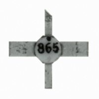
MGA-86576-STRG Avago Technologies US Inc., MGA-86576-STRG Datasheet - Page 4

MGA-86576-STRG
Manufacturer Part Number
MGA-86576-STRG
Description
IC AMP LNA MMIC GAAS SMD
Manufacturer
Avago Technologies US Inc.
Type
General Purpose Amplifierr
Datasheet
1.MGA-86576-STRG.pdf
(6 pages)
Specifications of MGA-86576-STRG
Noise Figure
1.6dB
Package / Case
4-SMD (Ceramic)
Current - Supply
22mA
Frequency
1.5GHz ~ 8GHz
Gain
20dB
P1db
6dBm
Rf Type
ISM
Test Frequency
4GHz
Voltage - Supply
5V
Mounting Style
SMD/SMT
Number Of Channels
1
Operating Frequency
8000 MHz
Operating Supply Voltage
5 V
Supply Current
22 mA @ 5 V
Manufacturer's Type
MMIC Amplifier
Frequency (max)
8GHz
Operating Supply Voltage (typ)
5V
Package Type
Case 76
Mounting
Surface Mount
Pin Count
4
Noise Figure (typ)
2.5@8000MHzdB
Lead Free Status / RoHS Status
Lead free / RoHS Compliant
Lead Free Status / RoHS Status
Lead free / RoHS Compliant, Lead free / RoHS Compliant
Other names
516-2131
516-2131-2
516-2131-2
516-2131-2
516-2131-2
Available stocks
Company
Part Number
Manufacturer
Quantity
Price
Company:
Part Number:
MGA-86576-STRG
Manufacturer:
AVAGO
Quantity:
20 000
Part Number:
MGA-86576-STRG
Manufacturer:
AVAGO/安华高
Quantity:
20 000
MGA-86576 Typical Noise Parameters
T
[3]
MGA-86576 Applications Information
Introduction
The MGA-86576 is a high gain, broad band, low noise
amplifier. The use of plated through holes or an equiva-
lent minimal inductance grounding technique placed
precisely under each ground lead at the device is highly
recom-mended. A minimum of two plated through holes
under each ground lead is preferred with four being highly
suggested. A long ground path to pins 2 and 4 will add
additional inductance which can cause gain peaking in the
2 to 4 GHz frequency range. T his can also be accompanied
by a decrease in stability. A suggested layout is shown in
Figure 7. The circuit is designed for use on 0.031 inch thick
FR-4/G-10 epoxy glass dielectric material.
Printed circuit board thickness is also a major consid-
eration. Thicker printed circuit boards dictate longer
plated through holes which provide greater undesired
inductance. The parasitic inductance associated with a
pair of plated through holes passing through 0.031 inch
thick printed circuit board is approximately 0.1 nH, while
the inductance of a pair of plated through holes passing
through 0.062 inch thick board is about 0.2 nH. Avago does
not recommend using the MGA-86576 MMIC on boards
thicker than 0.040 inch.
Figure 7. Layout for MGA-86576 Demonstration Amplifier.
PCB dimensions are 1.18 inches wide by 1.30 inches high.
4
C
Reference plane taken at point where leads meet body of package.
= 25°C, Z
Frequency
GHz
1.0
1.5
2.5
4.0
6.0
8.0
o
= 50 Ω, V
d
= 5 V
NF
2.1
1.6
1.5
1.6
1.8
2.1
dB
o
Mag.
0.56
0.54
0.47
0.38
0.28
0.22
[3]
,
Γopt
Ang.
107
27
31
40
54
77
The effects of inductance associated with the board
material are easily analyzed and very predict-able. As a
minimum, the circuit simulation should consist of the data
sheet S-Parameters and an additional circuit file describing
the plated through holes and any additional inductance
associated with lead length between the device and the
start of the plated through hole. To obtain a complete
analysis of the entire amplifier circuit, the effects of the
input and output microstriplines and bias decoupling
circuits should be incorporated into the circuit file.
Device Connections V
RF and DC connections are shown in Figure 8. DC power
is provided to the MMIC through the same pin used to
obtain RF output. A 50 Ω microstripline is used to connect
the device to the following stage or output connector.
A bias decoupling network is used to feed in V
simultaneously providing a DC block to the RF signal. The
bias decoupling network shown in Figure 8, consisting of
resistor R1, a short length of high impedance microstrip-
line, and bypass capacitor C1, provides the best overall
performance in the 2 to 8 GHz frequency range.
Figure 8. Demonstration Amplifier Schematic.
50 Ω
R
N
0.43
0.40
0.36
0.32
0.28
0.25
/50 Ω
27 pF
50 Ω
d
and RF Output (Pin 3)
L1
100-1000 pF
MGA-86576 fig 8
1
4
2
C1
R1
3
10-100 Ω
V
HIGH Z
dd
50 Ω
27 pF
50 Ω
dd
while


