0920AT50A080E Johanson Technology Inc, 0920AT50A080E Datasheet

ANTENNA CHIP ISM 920 MHZ

0920AT50A080E

Manufacturer Part Number
0920AT50A080E
Description
ANTENNA CHIP ISM 920 MHZ
Manufacturer
Johanson Technology Inc
Datasheets

Specifications of 0920AT50A080E

Antenna Type
Chip
Number Of Bands
1
Frequency
880MHz ~ 960MHz
Gain
-2.6dBi
Termination
Surface Mount
Mounting Type
Surface Mount
Height (max)
0.06" (1.7mm)
Impedance
50ohm
Bandwidth
80MHz
Power Rating
5W
Rohs Compliant
Yes
Lead Free Status / RoHS Status
Lead free by exemption / RoHS Compliant
Vswr
-
Other names
0920AT50A080
712-1002-2
Detail Specification: 09/15/05
General Specifications
Part Number
Frequency Range
Peak Gain
Average Gain
Return Loss
Mechanical Dimensions
Mounting Considerations
Mount these devices with brown mark facing up. Units: mm
Line width should be designed to provide 50Ω impedance matching characteristics.
920 MHz Antenna
W
L
T
a
b
c
0.433
0.201
0.059
0.039
0.020
0.020
5.5 mm
0 Ohm
In
a) Without Matching Circuits
±
±
±
±
±
±
1 mm
0.012
0.012
0.008
0.008
0.012
0.012
"High Frequency Ceramic Solutions"
Johanson Technology, Inc. reserves the right to make design changes without notice.
11.00
0.7 mm
5.10
1.50
1.00
0.50
0.50
All sales are subject to Johanson Technology, Inc. terms and conditions.
mm
0. 6mm
12.6 mm
±
±
±
±
±
±
9.6 mm
0920AT50A080
880 - 960 Mhz
-0.7 dBi typ. (XZ-V)
-2.6 dBi typ. (XZ-V)
8.5 dB min.
0.30
0.30
0.20
0.20
0.30
0.30
4.5 mm
1.5 mm
a
b
1.3 mm
931 Via Alondra • Camarillo, CA 93012 • TEL 805.389.1166 FAX 805.389.1821
0.8 mm
c
L
4.3 pF
Input Power
Impedance
Operating Temperature
Reel Quanity
0.7 mm
10 nH
2003 Johanson Technology, Inc. All Rights Reserved
3.9 pF
W
Via
b) With Matching Circuits
www.johansontechnology.com
0.7 mm
T
P/N 0920AT50A080
No.
Terminal Configuration
6
7
8
1
2
3
4
5
6
7
8
5W max.
50 Ω
-40 to +85°C
1,000
Feed Point
Function
NC
NC
NC
NC
NC
NC
NC
4
5
Page 1 of 4
1
2
3

Related parts for 0920AT50A080E

0920AT50A080E Summary of contents

Page 1

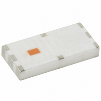
Frequency Ceramic Solutions" 920 MHz Antenna Detail Specification: 09/15/05 General Specifications 0920AT50A080 Part Number 880 - 960 Mhz Frequency Range -0.7 dBi typ. (XZ-V) Peak Gain -2.6 dBi typ. (XZ-V) Average Gain 8.5 dB min. Return Loss Mechanical Dimensions ...

Page 2

Frequency Ceramic Solutions" 920 MHz Antenna Detail Specification: 09/15/05 Typical Electrical Characteristics (T=25 Test Board 31.9 mm Return Loss a) Without Matching Circuit Johanson Technology, Inc. reserves the right to make design changes ...

Page 3

Frequency Ceramic Solutions" 920 MHz Antenna Detail Specification: 09/15/05 Typical Electrical Characteristics (T=25 Test Board 31.9 mm Return Loss b) With Matching Circuit Johanson Technology, Inc. reserves ...

Page 4

Frequency Ceramic Solutions" 920 MHz Antenna Detail Specification: 09/15/ XY-V/XY 90° Y 0° XY-cut scanning direction XZ-V/XZ-H Y 90° Z 0° XZ-cut scanning direction YZ-V/YZ-H X 90° 0° Z YZ-cut scanning direction ...

Related keywords