2450AT43A100E Johanson Technology Inc, 2450AT43A100E Datasheet
2450AT43A100E
Manufacturer Part Number
2450AT43A100E
Description
ANTENNA CHIP 2.4GHZ
Manufacturer
Johanson Technology Inc
Specifications of 2450AT43A100E
Antenna Type
Chip
Number Of Bands
1
Frequency
2.4GHz ~ 2.5GHz
Gain
0.5dBi
Termination
Surface Mount
Mounting Type
Surface Mount
Height (max)
0.05" (1.3mm)
Impedance
50ohm
Bandwidth
100MHz
Power Rating
3W
Rohs Compliant
Yes
Lead Free Status / RoHS Status
Lead free by exemption / RoHS Compliant
Vswr
-
Other names
2450AT43A100
712-1009-2
712-1009-2
Available stocks
Company
Part Number
Manufacturer
Quantity
Price
Company:

Part Number:
2450AT43A100E
Manufacturer:
NXP
Quantity:
60 000


Detail Specification: 12/21/03
General Specifications
Part Number
Frequency Range
Peak Gain
Average Gain
Return Loss
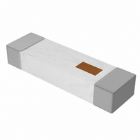
Mechanical Dimensions
Mounting Considerations
Mount these devices with brown mark facing up. Units: mm
* Line width should be designed to provide 50Ω impedance matching characteristics.
2.45 GHz Antenna
W
L
T
a
0.276
0.079
0.047
0.020
In
+.004/-.008
(Matching components, if used, will vary in value depending on PCB layout)
±
±
±
0.008
0.008
0.012
"High Frequency Ceramic Solutions"
Johanson Technology, Inc. reserves the right to make design changes without notice.
7.00
2.00
1.20
0.50
*
All sales are subject to Johanson Technology, Inc. terms and conditions.
mm
±
±
±
+0.1/-0.2
2450AT43A100
2400 - 2500 Mhz
2.0 dBi typ. (XZ-V)
0.5 dBi typ. (XZ-V)
9.5 dB min.
0.20
0.20
0.30
W
931 Via Alondra • Camarillo, CA 93012 • TEL 805.389.1166 FAX 805.389.1821
1.0
L
Input Power
Impedance
Operating Temperature
Reel Quanity
No.
1
2
8.0
5.5
Feeding Point
Function
2003 Johanson Technology, Inc. All Rights Reserved
NC
www.johansontechnology.com
2.0
P/N 2450AT43A100
2
Terminal Configuration
3W max.
50 Ω
-40 to +85°C
1,000
a
Page 1 of 3
T
1
Related parts for 2450AT43A100E
Image
Part Number
Description
Manufacturer
Datasheet
Request
R

Part Number:
Description:
COMMERCIAL THERMAL
Manufacturer:
Honeywell Sensing and Control
Part Number:
Description:
COMMERCIAL THERMAL
Manufacturer:
Honeywell Sensing and Control
Part Number:
Description:
COMMERCIAL THERMAL
Manufacturer:
Honeywell Sensing and Control
Part Number:
Description:
COMMERCIAL THERMAL
Manufacturer:
Honeywell Sensing and Control

Part Number:
Description:
Manufacturer:
Johanson Technology Inc
Datasheet:
2450AT43A100E Summary of contents
Page 1
Frequency Ceramic Solutions" 2.45 GHz Antenna Detail Specification: 12/21/03 General Specifications Part Number Frequency Range Peak Gain Average Gain Return Loss Mechanical Dimensions In mm 0.276 0.008 7.00 L ± ± W 0.079 ± 0.008 2.00 ± 0.047 1.20 ...
Page 2
Frequency Ceramic Solutions" 2.45 GHz Antenna Detail Specification: 12/21/03 Typical Electrical Characteristics (T= Test Board ) ) ) 20mm Return Loss Johanson Technology, Inc. reserves the right to make design changes without notice. All sales are ...
Page 3
Frequency Ceramic Solutions" 2.45 GHz Antenna Detail Specification: 12/21/ XY-V/XY 90° Y 0° XY-cut scanning direction XZ-V/XZ-H Y 90° Z 0° XZ-cut scanning direction YZ-V/YZ-H X 90° 0° Z YZ-cut scanning direction ...