ATR2406-DEV-BOARD Atmel, ATR2406-DEV-BOARD Datasheet - Page 7
ATR2406-DEV-BOARD
Manufacturer Part Number
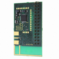
ATR2406-DEV-BOARD
Description
BOARD DEVELOPMENT FOR ATR2406
Manufacturer
Atmel
Series
Smart RFr
Type
Transceiver, ISMr
Datasheet
1.ATR2406-DEV-BOARD.pdf
(25 pages)
Specifications of ATR2406-DEV-BOARD
Frequency
2.4GHz
Wireless Frequency
2.4 GHz
Interface Type
SPI
Modulation
GFSK
Operating Voltage
2.9 V to 3.6 V
Antenna
F-Antenna, SMA
Operating Temperature Range
- 10 C to + 60 C
For Use With/related Products
ATR2406
Lead Free Status / RoHS Status
Contains lead / RoHS non-compliant


6. Electrical Characteristics (Continued)
V
4779N–ISM–12/08
Notes:
S
5.10
5.11
No.
5.1
5.2
5.3
5.4
5.5
5.6
5.7
5.8
5.9
6.1
6.2
7.1
7.2
7.3
= 3.6V with AUX regulator, T
5
6
7
Parameters
Receiver Part
RX input impedance
Sensitivity
Third order input intercept point
Intermodulation rejection
Co-channel rejection
Adjacent channel rejection
±1.728 MHz
Bi-adjacent channel rejection
±3.456 MHz
Rejection with
separation
Out of band rejection > 6 MHz
Out of band rejection
2300 MHz to 2394 MHz
2506 MHz to 2600 GHz
Out of band rejection
30 MHz to 2300 MHz
2600 MHz to 6 GHz
RSSI Part
Maximum RSSI output voltage
RSSI output voltage, monotonic
over range –96 dBm to –36 dBm
VCO
Oscillator frequency defined at
TX output
Frequency control voltage range
VCO tuning input gain defined at
TX output
1. Measured and guaranteed only on the Atmel
2. Timing is determined by external loop filter characteristics. Faster timing can be achieved by modification of the loop filter.
3. The Gaussian filter control setting (GFCS) is used to compensate production tolerances by tuning the modulation deviation
4. Burst mode with 0.9% duty cycle
±5.128 MHz
quency (Smart RF) firmware. Conducted measured.
For further information refer to the application notes.
in production to the nominal value of 400 kHz.
3 channels
amb
= 25°C, unless otherwise specified
Test Conditions
Differential
At input for BER
at 1152 kBits/s
BER < 10
level of interferers in channels
N + 2 and N + 4
BER < 10
BER < 10
adjacent level referred to wanted
channel level
BER < 10
bi-adjacent level referred to wanted
channel level
BER < 10
n
wanted channel level
BER < 10
2.45 GHz
BER < 10
2.45 GHz
BER < 10
2.45 GHz
Under high RX input signal level
With –33 dBm at RF input
With –96 dBm at RF input
Over full temperature range
3 adjacent level referred to
(1)
(1)
(1)
-3
-3
-3
-3
-3
-3
-3
-3
, wanted at -83 dBm,
, wanted at –76 dBm
, wanted at –76 dBm,
, wanted at –76 dBm,
, wanted at –76 dBm,
, wanted at –83 dBm at
, wanted at –83 dBm at
, wanted at –83 dBm at
(1)
(1)
(1)
®
(1)
evaluation board, including microstrip filter, balun, and Smart Radio Fre-
10
(1)
-3
(1)
(1)
Symbol
Bl
V
R
R
R
V
V
Bl
RSSImax
G
df>6MHz
IIP3
i (n
R
i (N – 1)
i (N – 2)
Bl
VTUNE
IM
Z
RSSI
VCO
near
CO
in
far
3
3)
2400
Min.
–11
0.5
32
14
30
40
38
47
57
170 + j0
Typ.
–93
–15
240
2.1
1.9
0.1
V
ATR2406
CC
Max.
2483
– 0.5
MHz/V
dBm
dBm
MHz
Unit
dBc
dBc
dBc
dBc
dBc
dBc
dBc
dBc
V
V
V
V
7
Related parts for ATR2406-DEV-BOARD
Image
Part Number
Description
Manufacturer
Datasheet
Request
R

Part Number:
Description:
IC IF ISM TXRX 2.4GHZ 32QFN
Manufacturer:
Atmel
Datasheet:

Part Number:
Description:
BOARD DEV FOR ATR2406/ATMEGA88
Manufacturer:
Atmel
Datasheet:

Part Number:
Description:
KIT DEMO FOR ATR2406/ATMEGA88
Manufacturer:
Atmel
Datasheet:

Part Number:
Description:
Atr2406 Low-if 2.4-ghz Ism Transceiver
Manufacturer:
ATMEL Corporation
Datasheet:

Part Number:
Description:
RF Transceiver COM.ISM-SMART RF 2.4GHZ ISM TRX
Manufacturer:
Atmel
Datasheet:

Part Number:
Description:
Manufacturer:
Atmel
Datasheet:


Part Number:
Description:
LOW IF .4 GHZ ISM TRANSCEIVER
Manufacturer:
ATMEL [ATMEL Corporation]
Datasheet:

Part Number:
Description:
DEV KIT FOR AVR/AVR32
Manufacturer:
Atmel
Datasheet:
Part Number:
Description:
INTERVAL AND WIPE/WASH WIPER CONTROL IC WITH DELAY
Manufacturer:
ATMEL Corporation
Datasheet:
Part Number:
Description:
Low-Voltage Voice-Switched IC for Hands-Free Operation
Manufacturer:
ATMEL Corporation
Datasheet:
Part Number:
Description:
MONOLITHIC INTEGRATED FEATUREPHONE CIRCUIT
Manufacturer:
ATMEL Corporation
Datasheet:
Part Number:
Description:
AM-FM Receiver IC U4255BM-M
Manufacturer:
ATMEL Corporation
Datasheet:
Part Number:
Description:
Monolithic Integrated Feature Phone Circuit
Manufacturer:
ATMEL Corporation
Datasheet: