CGH40120F-TB Cree Inc, CGH40120F-TB Datasheet - Page 2
CGH40120F-TB
Manufacturer Part Number
CGH40120F-TB
Description
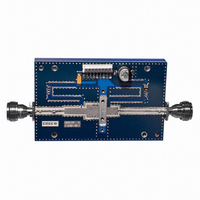
BOARD DEMO AMP CIRCUIT CGH40120
Manufacturer
Cree Inc
Type
HEMTr
Datasheet
1.CGH40120F.pdf
(13 pages)
Specifications of CGH40120F-TB
Mfg Application Notes
Thermal Performance Guide
Frequency
0Hz ~ 4GHz
For Use With/related Products
CGH40120F
Lead Free Status / RoHS Status
Contains lead / RoHS non-compliant


Absolute Maximum Ratings (not simultaneous) at 25˚C Case Temperature
Note:
1
2
3
Electrical Characteristics (T
Notes:
1
2
3
4
5
Copyright © 2008-2011 Cree, Inc. All rights reserved. The information in this document is subject to change without notice. Cree and
the Cree logo are registered trademarks of Cree, Inc.
Parameter
Drain-Source Voltage
Gate-to-Source Voltage
Storage Temperature
Operating Junction Temperature
Maximum Forward Gate Current
Soldering Temperature
Screw Torque
Thermal Resistance, Junction to Case
Case Operating Temperature
Characteristics
DC Characteristics
Gate Threshold Voltage
Gate Quiescent Voltage
Saturated Drain Current
Drain-Source Breakdown Voltage
RF Characteristics
Small Signal Gain
Power Output
Drain Efficiency
Output Mismatch Stress
Dynamic Characteristics
Input Capacitance
Output Capacitance
Feedback Capacitance
2
Refer to the Application Note on soldering at
Measured for the CGH40120F at P
See also, the Power Dissipation De-rating Curve on Page 7.
Measured on wafer prior to packaging.
Scaled from PCM data.
P
Drain Efficiency = P
Measured in CGH40120F-TB.
SAT
is defined as I
CGH40120F Rev 2.2
4
5
3
1
(T
1
G
2
C
= 25
OUT
= 2.8 mA.
2,3
/ P
˚
C, F
DC
0
2
= 1.3 GHz unless otherwise noted)
Symbol
VSWR
V
V
P
V
G
C
C
C
GS(th)
GS(Q)
I
DISS
DS
SAT
η
GD
BR
SS
GS
DS
C
= 112 W.
= 25˚C)
Min.
23.2
17.5
-3.8
120
100
Symbol
55
www.cree.com/products/wireless_appnotes.asp
–
–
–
–
–
I
V
T
V
R
GMAX
T
T
T
STG
τ
DSS
θJC
GS
J
S
C
Typ.
28.0
35.3
-3.3
-3.0
120
9.1
1.6
19
70
–
–
10 : 1
Max.
-2.3
–
–
–
–
–
–
–
–
–
-65, +150
-40, +150
-10, +2
Rating
225
245
1.5
84
30
80
Units
V
V
V
dB
%
pF
pF
pF
W
Y
A
DC
DC
DC
Conditions
V
V
V
V
V
V
V
No damage at all phase angles,
V
P
V
V
V
OUT
DS
DS
DS
GS
DD
DD
DD
DD
DS
DS
DS
= 10 V, I
= 28 V, I
= 6.0 V, V
= -8 V, I
= 28 V, I
= 28 V, I
= 28 V, I
= 28 V, I
= 28 V, V
= 28 V, V
= 28 V, V
= 100 W CW
D
D
D
DQ
DQ
DQ
DQ
gs
gs
gs
GS
= 28.8 mA
= 28.8 mA
= 1.0 A
= -8 V, f = 1 MHz
= -8 V, f = 1 MHz
= -8 V, f = 1 MHz
= 1.0 A
= 1.0 A
= 1.0 A, P
= 1.0 A,
= 2.0 V
USA Tel: +1.919.313.5300
Units
˚C/W
in-oz
Volts
Volts
www.cree.com/wireless
mA
Fax: +1.919.869.2733
˚C
˚C
˚C
˚C
Durham, NC 27703
OUT
4600 Silicon Drive
= P
SAT
Cree, Inc.
Related parts for CGH40120F-TB
Image
Part Number
Description
Manufacturer
Datasheet
Request
R

Part Number:
Description:
CGH40120, 120W, GaN HEMT By Cree For General Purpose (Wireless
Manufacturer:
Cree Inc
Datasheet:

Part Number:
Description:
CREE PLCC4 SMD LED WHITE
Manufacturer:
Cree Inc
Datasheet:
Part Number:
Description:
CREE PLCC4 SMD LED WHITE
Manufacturer:
Cree Inc
Datasheet:

Part Number:
Description:
CREE PLCC4 SMD LED WHITE
Manufacturer:
Cree Inc
Datasheet:
Part Number:
Description:
CREE PLCC4 SMD LED WHITE
Manufacturer:
Cree Inc
Datasheet:
Part Number:
Description:
CREE PLCC4 SMD LED WHITE
Manufacturer:
Cree Inc
Datasheet:

Part Number:
Description:
DIODE SCHOTTKY 600V 16.5A TO-247
Manufacturer:
Cree Inc
Datasheet:

Part Number:
Description:
DIODE SCHOTTKY 600V 6A TO220-2
Manufacturer:
Cree Inc
Datasheet:
Part Number:
Description:
DIODE SCHOTTKY 600V 10A TO220-2
Manufacturer:
Cree Inc
Datasheet:

Part Number:
Description:
IC AMP MMIC HEMT 25W 780019PKG
Manufacturer:
Cree Inc
Datasheet:

Part Number:
Description:
Cree� EZBright290� LEDs
Manufacturer:
CREE [Cree, Inc]
Datasheet:

Part Number:
Description:
DIODE SCHOT 600V 2A ZREC TO220
Manufacturer:
Cree Inc
Datasheet:
Part Number:
Description:
DIODE SCHOT 600V 3A ZREC TO252
Manufacturer:
Cree Inc
Datasheet: